tekmar 365 Mixing Control User Manual
Page 12
Copyright © D 365 - 06/00
12 of 16
Heat Demand switch
When the heating system uses zone valve end switches or some other means of delivering an external
heat demand signal to terminals
Heat Dem — Heat Dem (1 and 2), set this switch to "External Heat
Demand" and the control will only operate the system pump, boiler and mixing device when it receives
a 24/120 Vac signal from the heat demand circuit. If a 10K Zone control (tekmar 366) is connected
to terminals 10K Sen — Com Sen (14 and 15), the zone control may also call for heat.
If an external heat demand signal is not used, set the switch to "Permanent" and the control will be
enabled all the time unless a 10K zone control is connected.
Maximum Supply temperature
This setting determines the maximum allowable supply temperature to be delivered to the system.
When the supply temperature becomes too hot, the variable speed pump slows down – or the mixing
valve closes – until the temperature is stabilized at the maximum. To get the fastest system heat up
times, this setting should be set as high as allowable. Refer to page 6 for more details on maximum
supply operation and requirements.
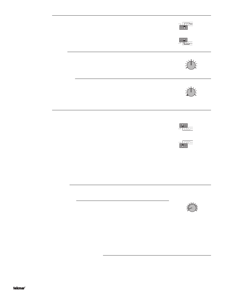
Minimum Boiler Return temperature
When a Boiler Return Sensor 071 is connected to the control, and the dial is turned up from "Off", this
setting determines the minimum allowable boiler return temperature. When the boiler return
temperature becomes too cold, the variable speed pump slows down – or the mixing valve is closed –
until the temperature is stabilized at the minimum. To minimize standby losses and get the fastest
system heat up times, this setting should be set as low as allowable. Refer to page 6 for more details
on minimum boiler return operation and requirements.
Boiler Enable switch
The position of this switch determines at which pump/valve position the control will fire the boiler under
normal conditions. If there is a Return Sensor 071 installed and the return temperature is too cold,
the control will immediately turn on the boiler in order to raise the water temperature more quickly.
At the "10% open" position, the control will not fire the boiler until the pump/valve has opened at least
10%, and will turn the boiler off when the pump/valve closes to 5% open. This setting would normally
be chosen for high mass boilers (cast iron, steel fire tube, etc.), or systems with a large thermal mass
in the loop between the boiler and the mixing pump/valve.
At the "25% open" position, the control will not fire the boiler until the valve has opened at least 25%,
and will turn the boiler off when the valve closes to 15% open. This setting would normally be chosen
for low mass boilers (copper fin tube, etc.), and systems with low thermal mass in the loop between the
boiler and the mixing pump/valve.
Zone Control
Boiler on when 25% open
External Heat Demand
Setpoint
1
2
3
4
Reset
Permanent Heat Demand
Indoor Sensor
Boiler on when 10% open
1
2
3
4
Reset
Permanent Heat Demand
Indoor Sensor
Boiler on when 10% open
1
2
3
4
Zone Control
Boiler on when 25% open
External Heat Demand
Setpoint
1
2
3
4
Motor Speed/ Pump Response (variable speed pump)
When using a variable speed system pump, this dial adjusts the amount of time required for the injection pump to go from 0%
to 100% flow when maximum output is required, and from 100% back to 0% when no output is required. The output response
of the variable speed pump depends on the magnitude of the controlling error (calculated from the readings the control is receiving
from the sensors).
Experimentation may be necessary in some systems to avoid instability (pump continually ramping up to 100% output and back
down), but most standard heating installations work best with settings in the 30 to 50 second range.
Motor Speed/ Pump Response
The type of device being controlled, and the length of time required for the system to respond to a
control action will determine the setting for this dial.
Motor Speed (4-20 mA valve output)
When operating a valve, the control uses the information from this setting to synchronize the firing of
the boiler to the valve position. Set this adjustment to match the time required for the actuating motor
to drive from the fully closed to the fully open position.
If you are unsure of the opening time, complete the following procedure:
(1) Make sure the actuating motor/mixing valve is in the fully closed position.
(2) Set the "Motor Speed/Pump Response" dial to the longest (fully clockwise) position.
(3) Power up the control and push the Test Button.
(4) Observe the motor as it is driven open by the test routine. When the motor reaches its fully open position by stopping against
its end switch, turn the dial down just until the control cycles through to the next step in the test routine.
(5) The "Motor Speed/Pump Response" dial is now set to the operating speed of the actuating motor. Let the control cycle through
to the end of the test routine.
Motor Speed /
Pump Response
130 sec.
30
230
Note:
Some heating systems combine high input, low mass boilers with very little thermal mass in the loop between the boiler
and mixing pump/valve. In some extreme cases, erratic boiler action (short cycling and tripping of high limits) may result
from this type of system even at the "25% open" position. To prevent this type of operation it may be necessary to add
thermal mass to the system by installing a storage tank or making the loop larger.
150
°F
100
200
Max./Setpoint
Minimum
Boiler Return
Off
100
°F
150
60