Step five – tekmar 365 Mixing Control User Manual
Page 10
Copyright © D 365 - 06/00
10 of 16
Test the outputs
If a System Pump circuit is connected to the
Sys Pmp — Sys Pmp (5 and 6) terminals; make sure power to the circuit is off and
install a jumper in the terminal plug between terminals 5 and 6. When the system Pump circuit is powered-up, the pump should
operate. If it does not come on, check the circuit wiring for errors and ensure that it is powered up and the voltage is correct. Check
the devices in the circuit (pump, switching relay, etc.) for faults. If the pump operates properly when the circuit is powered up
disconnect the power, remove the jumper and proceed to the next step.
Note: When a Return Sensor 071 is used, the boiler loop pump must operate with the system pump. See Brochure A 365.
If you are using the control to operate the boiler; make sure power to the boiler circuit is off and install a jumper in the terminal plug
between the
Boiler (8 and 9) terminals. When the boiler circuit is powered-up, the boiler should operate. If it does not come on,
check the circuit wiring for errors and ensure that it is powered up and the voltage is correct. Check the devices in the circuit (limits,
flow switches, etc.) for faults. If the boiler operates properly when the circuit is powered up, disconnect the power, remove the jumper
and proceed to the next step.
If a Variable Speed Pump is connected to the
Power N — Var Pmp (3 and 7) terminals; make sure power to the circuit is off and
install a jumper in the terminal plug between
L —Var Pmp (4 and 7) terminals. When 120 Vac supply is powered up, the variable
speed pump should operate. If the pump operates properly when the circuit is powered up, disconnect the power, remove the jumper
and proceed to the next step. During operation, this output from the control can be measured with a standard voltmeter. Push the
test button, and monitor the voltage at terminals 3 & 7.
At 100% output the voltage should read between 90 and 130Vac.
Step Five
Testing the wiring
Caution
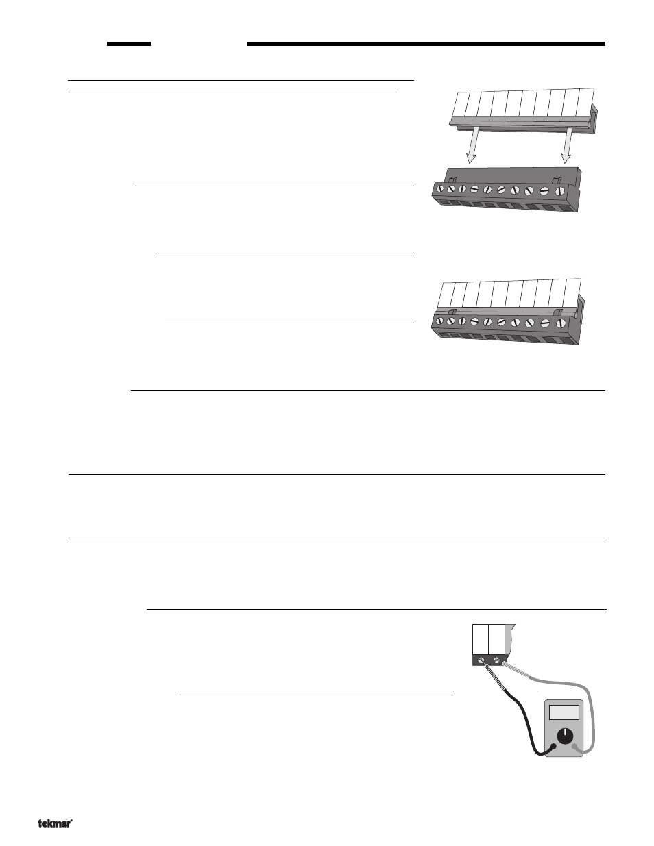
Before applying power to the control for testing, each terminal plug must be
unplugged from its header on the control. Pull straight down to unplug.
These tests are to be performed using standard electrical testing practices and
procedures and should only be carried out by properly trained and experi-
enced persons.
A good quality electrical test meter, capable of reading from at least 0 — 200
Volts AC, and at least 0 — 1,000,000 Ohms, is essential to properly test this
control.
Test the sensors
These test must be made
before turning on the power supply, and with the terminals
unplugged. The sensors are to be tested according to the instructions in brochure
D 001. If a tekmar RTU or Zone Control is used, check the applicable data brochure
for the product used.
Test the power supply
Make sure exposed wiring or bare terminals are not in contact with any other wires or
grounded surfaces. Turn on the 120 Vac power and use an AC voltmeter to measure
the voltage between terminals
N — L (3 and 4). Between 110 and 130 Vac should be
measured at these terminals.
Test the powered inputs
If an external Heat Demand signal is used, power up the Heat Demand circuit and
supply a Heat Demand signal to the control. Use an AC voltmeter to measure the
voltage between terminals
Heat Dem — Heat Dem (1 and 2). From 22 to 130 Volts AC
should be measured at these terminals.
Terminal plug disconnected
from its header on the control
Connect the control
Turn the power off and make sure all test jumpers have been removed from the plugs.
• Connect the plugs to the control by carefully aligning them with their respective headers and
pushing them upwards into the headers. The plugs should snap firmly into place.
• Install the supplied safety divider(s) between low voltage and high voltage wiring chambers.
• The control is now ready for set-up and operation.
Testing the 4-20 mA output
The 4-20 mA output terminals (10 and 11) cannot be tested without power being applied to
the control. If you are going to be using this output, connect an ammeter to the 4-20 mA output
terminals (10 and 11) and observe the current reading during operation. Refer to the
Sequence of Operation section of this brochure for details on 4-20 mA output levels.
Caution
The tekmar Mixing Reset Control 365 is an operating control and is not certified or intended for use as a safety device.
Under no circumstances should safety limit devices be left disconnected after installation of this control. The installer
shall check all applicable code requirements and obtain necessary inspections to ensure that the installation is in
compliance with those requirements.
Milli Amp
6.4 mA
Test the output
using a
milliamp meter
1000 mA = 1 amp
Measuring
the 4-20 mA
Output
11
10
+
4-20 Com
–
R
S
1
12 13
14
16
15
17
18 19
2K
RTU
Sup
Sen
Ret
Sen
Uno
Sw
10K
Sen
Com
Sen
Out
Sen
11
Com
–
Com
Sen
10
4-20
+
Terminal plug pushed into
its header on the control
12
13
14
16
15
17
18 19
2K
RTU
Sup
Sen
Ret
Sen
Uno
Sw
10K
Sen
Com
Sen
Out
Sen
11
Com
–
Com
Sen
10
4-20
+