Error messages, Step nine – tekmar 365 Mixing Control User Manual
Page 15
Copyright © D 365 - 06/00
15 of 16
Step Nine
Before you leave
• Install the wiring cover over the wiring chamber and secure it to the base with the two screws provided. Place the front cover
on the control to cover the setting dials and snap it into place. Install a lock if security is required.
• Place this brochure, and all other brochures relating to the installation, in the protective plastic bag supplied with the control.
Place the bag in a conspicuous location near the control for future reference.
• It is important to explain the operation and maintenance of this control and of the system to the end user and anyone else who
may be operating the system.
• If a Boiler Return Sensor is connected and an open circuit develops, or if no sensor is installed but the "Minimum Boiler Return"
dial is set up from the off position. An error message will then be displayed (see error messages).
• If a short circuit develops at the boiler return sensor terminals, the Boiler Return function will become inactive. An error message
will then be displayed (see error messages).
After any repair has been completed, press the Test button to confirm that correct operation has been restored.
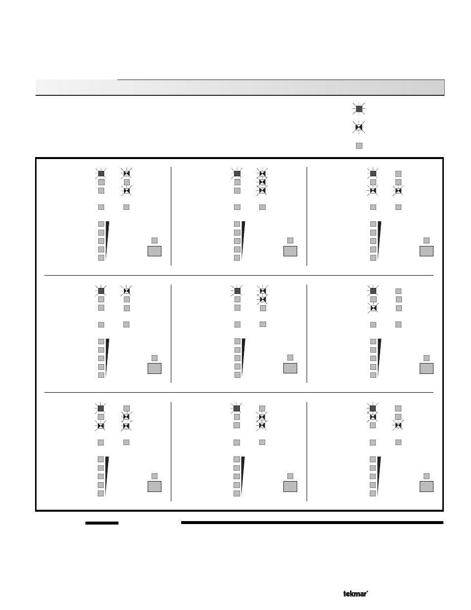
Error Messages
Whenever a fault is detected in any of the sensors, the indicator lights will flash in specific ways,
indicating the location of the problem. The following look-up table describes each error condition
and shows the flashing light sequence that results. After repairing the problem, press the Test
button to cycle the control through the test routine. This will confirm that the fault has been
repaired and that correct control action has been restored. For detailed sensor testing
instructions see Data Brochure D 001.
Light on continuously
Light flashing
Light off
Outdoor
Sensor
short
circuit
(see
trouble-
shooting
notes)
Supply
Sensor
short
circuit
(see
trouble-
shooting
notes)
Boiler
Return
Sensor
short
circuit
(see
trouble-
shooting
notes)
Boiler
Return
Sensor
open
circuit
(see
trouble-
shooting
notes)
Supply
Sensor
open
circuit
(see
trouble-
shooting
notes)
Outdoor
Sensor
open
circuit
(see
trouble-
shooting
notes)
RTU
short
circuit
(see
trouble-
shooting
notes)
10K
Indoor
sensor
short
circuit
(see
trouble-
shooting
notes)
Enclosure
Over-
heated
(see
trouble-
shooting
notes)
90
70
50
30
10
Power
WWSD
UnOcc.
Switch
Min.
Return
Boiler
Heat
Demand
Max. or
Setpoint
Pump
%
of full
output
Test
Power
WWSD
UnOcc.
Switch
Min.
Return
Boiler
Heat
Demand
Max. or
Setpoint
Pump
%
of full
output
Test
90
70
50
30
10
Power
WWSD
UnOcc.
Switch
Min.
Return
Boiler
Heat
Demand
Max. or
Setpoint
Pump
%
of full
output
Test
90
70
50
30
10
Power
WWSD
UnOcc.
Switch
Min.
Return
Boiler
Heat
Demand
Max. or
Setpoint
Pump
%
of full
output
Test
90
70
50
30
10
Power
WWSD
UnOcc.
Switch
Min.
Return
Boiler
Heat
Demand
Max. or
Setpoint
Pump
%
of full
output
Test
90
70
50
30
10
Power
WWSD
UnOcc.
Switch
Min.
Return
Boiler
Heat
Demand
Max. or
Setpoint
Pump
%
of full
output
Test
90
70
50
30
10
Power
WWSD
UnOcc.
Switch
Min.
Return
Boiler
Heat
Demand
Max. or
Setpoint
Pump
%
of full
output
Test
90
70
50
30
10
Power
WWSD
UnOcc.
Switch
Min.
Return
Boiler
Heat
Demand
Max. or
Setpoint
Pump
%
of full
output
Test
90
70
50
30
10
Power
WWSD
UnOcc.
Switch
Min.
Return
Boiler
Heat
Demand
Max. or
Setpoint
Pump
%
of full
output
Test
90
70
50
30
10