With heat demand signal, With no heat demand signal – tekmar 365 Mixing Control User Manual
Page 6
Copyright © D 365 - 06/00
6 of 16
90
70
50
30
10
Power
WWSD
UnOcc.
Switch
Min.
Return
Boiler
Heat
Demand
Max. or
Setpoint
Pump
%
of full
output
90
70
50
30
10
Power
WWSD
UnOcc.
Switch
Min.
Return
Boiler
Heat
Demand
Max. or
Setpoint
Pump
%
of full
output
OR
90
70
50
30
10
Power
WWSD
UnOcc.
Switch
Min.
Return
Boiler
Heat
Demand
Max. or
Setpoint
Pump
%
of full
output
90
70
50
30
10
Power
WWSD
UnOcc.
Switch
Min.
Return
Boiler
Heat
Demand
Max. or
Setpoint
Pump
%
of full
output
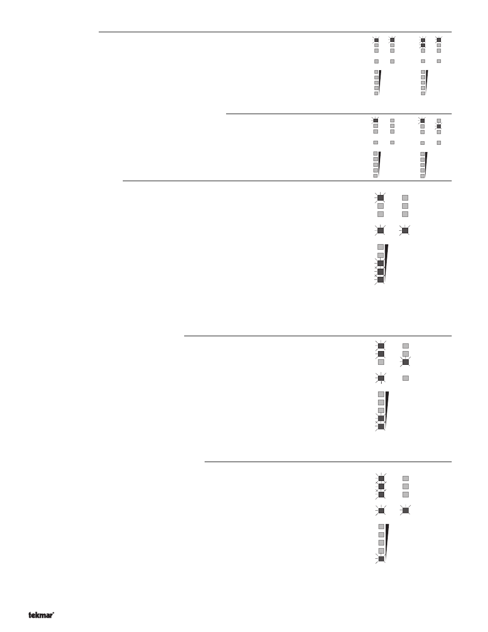
UnOcc. Switch light may also be on
Any or all "% of Full Output" LEDs may also be on
Boiler light may also be on
UnOcc. Switch light may also be on
Any or all "% of Full Output" LEDs may also be on
WWSD function
When WWSD occurs, the "WWSD" light will come on, the 4-20 mA will go to 4 mA, the
variable speed pump will be off, and the boiler and system pump will shut down. The control
will continue to monitor the outdoor and supply temperatures. Whenever 3 days pass with
the control in uninterrupted WWSD, the system pump will be cycled on for 10 seconds, the
4 to 20 mA mixing valve (if used) will be run open and then closed to help prevent seizing,
and the variable speed pump (if used) will be turned fully on and then ramped off again. If
a tekmar zone control is connected to this control, the system pump will only be turned off
when the zone control does not require heat or the valve/injection pump is being exercised.
With Heat Demand signal
The "Heat Demand" light will come on, the control will switch on the system pump and boiler, and
calculate the desired supply temperature based on the requirements of the Heating Curve.
The control will operate the 4-20 mA output and the variable speed pump to deliver the correct
supply temperature. The 4-20 mA and variable speed pump output levels are displayed on the
"% of full output" LEDs.
When controlling the 4-20 mA / variable speed pump, the control acts as follows:
(a) - To increase the supply temperature. The 4-20 mA drive and variable speed pump output
levels will increase at a rate determined by the control. The maximum rate is set at the Motor
Speed/Pump Response dial.
(b) - To decrease the supply temperature. The 4-20 mA drive and variable speed pump output
levels will decrease at a rate determined by the control. The maximum rate is set at the
Motor Speed/Pump Response dial.
(c) - To maintain a steady supply temperature. The 4-20 mA drive and the variable speed pump
output levels will remain relatively constant provided the heating load and boiler tempera-
ture does not change significantly.
Maximum Supply temperature operation
To provide a measure of protection to system components that may be damaged by excessive
heat, (e.g.. some types of plastic pipe) this control has a setting for Maximum Supply temperature.
When the supply temperature is close to the setting on the Max./Setpoint dial, the control will
reduce the "% of output" in order to keep the supply water temperature below the maximum
setting. At this time the "Max. or Setpoint" light will come on.
The control may operate for a long time at the Maximum temperature if:
(a) - it is coming out of a deep setback or just starting up from a cold start;
(b) - an RTU (or Occupied dial when Indoor Sensor 074 is used) is turned up suddenly; or
(c) - the maximum setting is too low for system design conditions.
Minimum Boiler Return temperature operation
To provide a measure of protection to boilers that may have minimum return water temperature
requirements, this control has a setting for Minimum Boiler Return temperature.
When the boiler return temperature is close to the setting on the Minimum Boiler Return dial, the
control will decrease the "% of output" in order to increase the boiler return temperature and
prevent undershoot. The "Min. Return" light will come on and the control will continue to decrease
the output in order to maintain the temperature slightly above the Minimum Boiler Return
temperature setting. The "Boiler" light will be on as the control continues to fire the boiler (even
below the 10%/25% open settings) in order to raise the return temperature.
The control may operate for a long time at the Minimum temperature if:
(a) - it is coming out of a deep setback or just starting up from a cold start;
(b) - an RTU (or Occupied dial when Indoor Sensor 074 is used) is turned up suddenly;
(c) - the Minimum setting is too high for system design conditions; or
(d) - the boiler aquastat is set lower than the "Minimum Boiler Return" dial setting.
90
70
50
30
10
Power
WWSD
UnOcc.
Switch
Min.
Return
Boiler
Heat
Demand
Max. or
Setpoint
Pump
%
of full
output
UnOcc. Switch
light may also be on
Outdoor temperature cold enough to require heating
Occupied/Unoccupied dial:
With no Heat Demand signal
When the outdoor temperature is colder than the WWSD point, the control will leave
WWSD. Whenever the control leaves WWSD, the "WWSD" light will go out and the control
will continue to monitor the outdoor and supply temperatures, but no further control action
will take place unless there is a heat demand signal.
90
70
50
30
10
Power
WWSD
UnOcc.
Switch
Min.
Return
Boiler
Heat
Demand
Max. or
Setpoint
Pump
%
of full
output
90
70
50
30
10
Power
WWSD
UnOcc.
Switch
Min.
Return
Boiler
Heat
Demand
Max. or
Setpoint
Pump
%
of full
output
OR
UnOcc.
Switch
light may
also be on
Pump
light may
also be on