Tap ac switching characteristics, Tap timing and test conditions – Cypress CY7C1312AV18 User Manual
Page 17
CY7C1310AV18
CY7C1312AV18
CY7C1314AV18
PRELIMINARY
Document #: 38-05497 Rev. *A
Page 17 of 21
TAP AC Switching Characteristics
Over the Operating Range
[26, 27]
Parameter
Description
Min.
Max.
Unit
t
TCYC
TCK Clock Cycle Time
100
ns
t
TF
TCK Clock Frequency
10
MHz
t
TH
TCK Clock HIGH
40
ns
t
TL
TCK Clock LOW
40
ns
Set-up Times
t
TMSS
TMS Set-up to TCK Clock Rise
10
ns
t
TDIS
TDI Set-up to TCK Clock Rise
10
ns
t
CS
Capture Set-up to TCK Rise
10
ns
Hold Times
t
TMSH
TMS Hold after TCK Clock Rise
10
ns
t
TDIH
TDI Hold after Clock Rise
10
ns
t
CH
Capture Hold after Clock Rise
10
ns
Output Times
t
TDOV
TCK Clock LOW to TDO Valid
20
ns
t
TDOX
TCK Clock LOW to TDO Invalid
0
ns
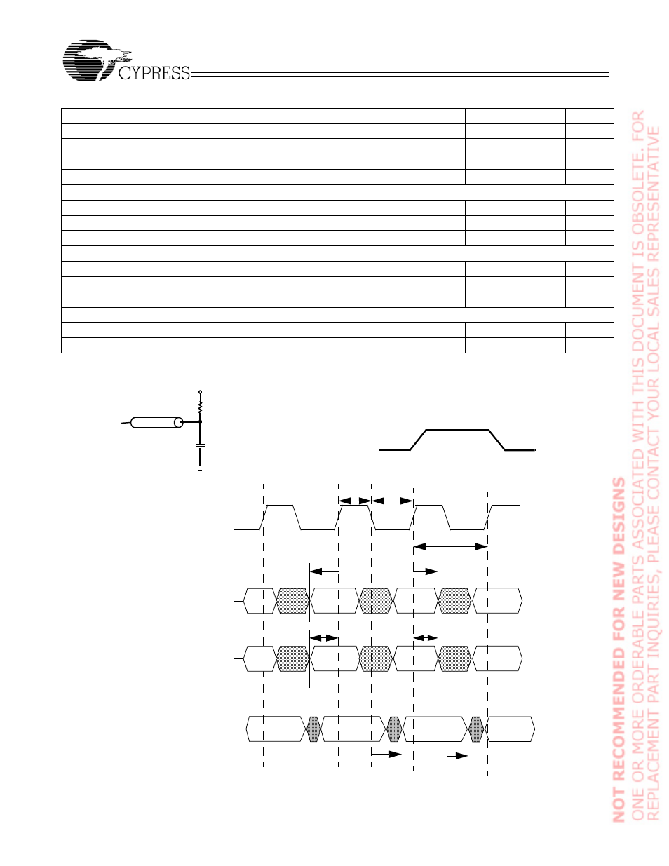
TAP Timing and Test Conditions
26. t
CS
and t
CH
refer to the set-up and hold time requirements of latching data from the boundary scan register.
27. Test conditions are specified using the load in TAP AC test conditions. t
R
/t
F
= 1 ns.
(a)
TDO
C
L
= 20 pF
Z
0
= 50
Ω
GND
0.9V
50
Ω
1.8V
0V
ALL INPUT PULSES
0.9V
Test Clock
Test Mode Select
TCK
TMS
Test Data-In
TDI
Test Data-Out
t
TCYC
t
TMSH
t
TL
t
TH
t
TMSS
t
TDIS
t
TDIH
t
TDOV
t
TDOX
TDO