Sequence of operation – tekmar 261 Boiler Control User Manual
Page 4
Copyright © D 261 - 0
3/09
4 of 20
Sequence of Operation
Section A
General Operation
Page 4
Section B
Boiler Reset
Page 5-8
Section C
Setpoint
Page 8
Section A — General Operation
POWERING UP THE CONTROL
When the Boiler Control 261 is powered up, the control displays the control type number in the LCD for 2 seconds. Next, the software
version is displayed for 2 seconds. Finally, the control enters into the normal operating mode and the LCD defaults to displaying the
current outdoor air temperature.
OPERATION
The 261 operates two on / off heat sources to control the supply water
temperature to a hydronic system. The supply water temperature is based
on either the current outdoor temperature, or a fixed setpoint.
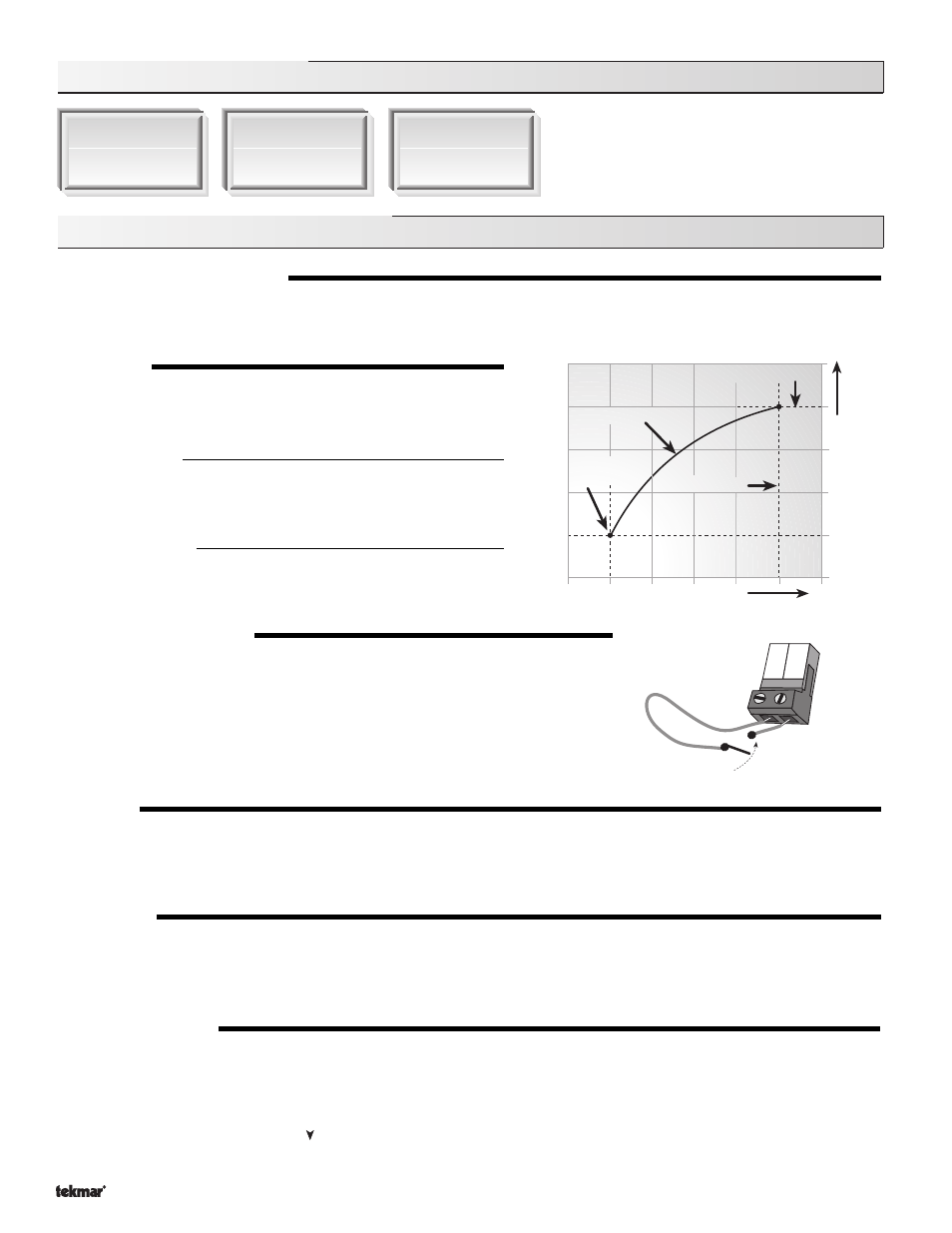
Outdoor Reset
When a demand signal from the heating system is present, the 261
calculates a supply temperature based on the outdoor air tempera-
ture and
Characterized Heating Curve settings.
Setpoint Control
When a demand signal from a setpoint system is present, the control
operates the boiler(s) to maintain the supply water temperature at the
Setpoint setting. Refer to section C.
SETBACK (UNOCCUPIED)
To provide greater energy savings, the 261 has a setback capability. With setback, the
supply water temperature in the system is reduced when the building is unoccupied. By
reducing the supply water temperature, air temperature in the space may be reduced
even when thermostat(s) are not turned down. Any time the
UnO Sw (13) and the Com
(14) terminals are shorted together, the control operates in the unoccupied (Night) mode.
When in the unoccupied (Night) mode, the UNOCC segment is displayed in the LCD. The
261 adjusts the supply water temperature based on the UNOCC settings made in the control.
This feature has no effect when the control is used in setpoint operation.
ROTATION
The 261’s
Equal Run Time Rotation function is fixed at 48 hours. The firing order of the boilers changes whenever one stage accumulates
48 hours more running time than the other stage. After each rotation, the stage with the least running hours is the first to fire, and the
stage with the most running hours is the last to fire. This function ensures that both stages receive equal amounts of use. When the
Rotate / Off DIP switch is set to the Off position, Stage 1 is always the first stage to fire.
EXERCISING
The 261 has a built-in exercising function. If the pump has not been operated at least once every 3 days, the control turns on the
output for 10 seconds. This minimizes the possibility of the pump seizing during a long period of inactivity. While the control is
exercising, the
Test LED flashes.
Note: The exercising function does not work if power to the control or pump is disconnected.
FACTORY DEFAULTS
The control comes preset with several factory defaults. These defaults are based on the terminal unit selection (see section B2). To
fine-tune building requirements, these defaults may be changed. If a factory default value for a terminal unit is changed, the terminal
unit number will flash when selected in the ADJUST menu.
To reload the factory defaults listed in section B2, power down the control and wait for 10 seconds. Power up the control while
simultaneously holding the
Item and buttons. The terminal unit number should now be displayed constantly in the LCD rather
than flashing.
Outdoor Design
Increasing W
ater
T
emperature
Design Supply
Decreasing Outdoor Temperature
Terminal Unit
Indoor Design
13 14
Timer switch
UnO
Sw
Com