tekmar 261 Boiler Control User Manual
Page 11
Copyright © D 261 - 0
3/09
11 of 20
Unoccupied Switch
If an external timer (tekmar Timer 032) or switch is used, connect the two wires from
the external switch to the
UnO Sw and Com terminals (13 and 14). When these two
terminals are shorted together, the control registers an unoccupied signal.
STEP FIVE
TESTING THE WIRING
Each terminal block
must be unplugged from its header on the control before power is applied for testing. To remove a terminal
block, pull it straight down from the control.
The following tests are to be performed using standard testing practices and procedures, and should only be carried out by properly
trained and experienced persons.
A good quality electrical test meter, capable of reading from at least 0 - 300 V (ac) and at least 0 - 2,000,000 Ohms, is essential to
properly test the wiring and sensors.
Test The Sensors
In order to test the sensors, the actual temperature at each sensor
location must be measured. A good quality digital thermometer with a
surface temperature probe is recommended for ease of use and
accuracy. Where a digital thermometer is not available, a spare sensor
can be strapped alongside the one to be tested, and the readings
compared. Test the sensors according to the instructions in the Data
Brochure D 070.
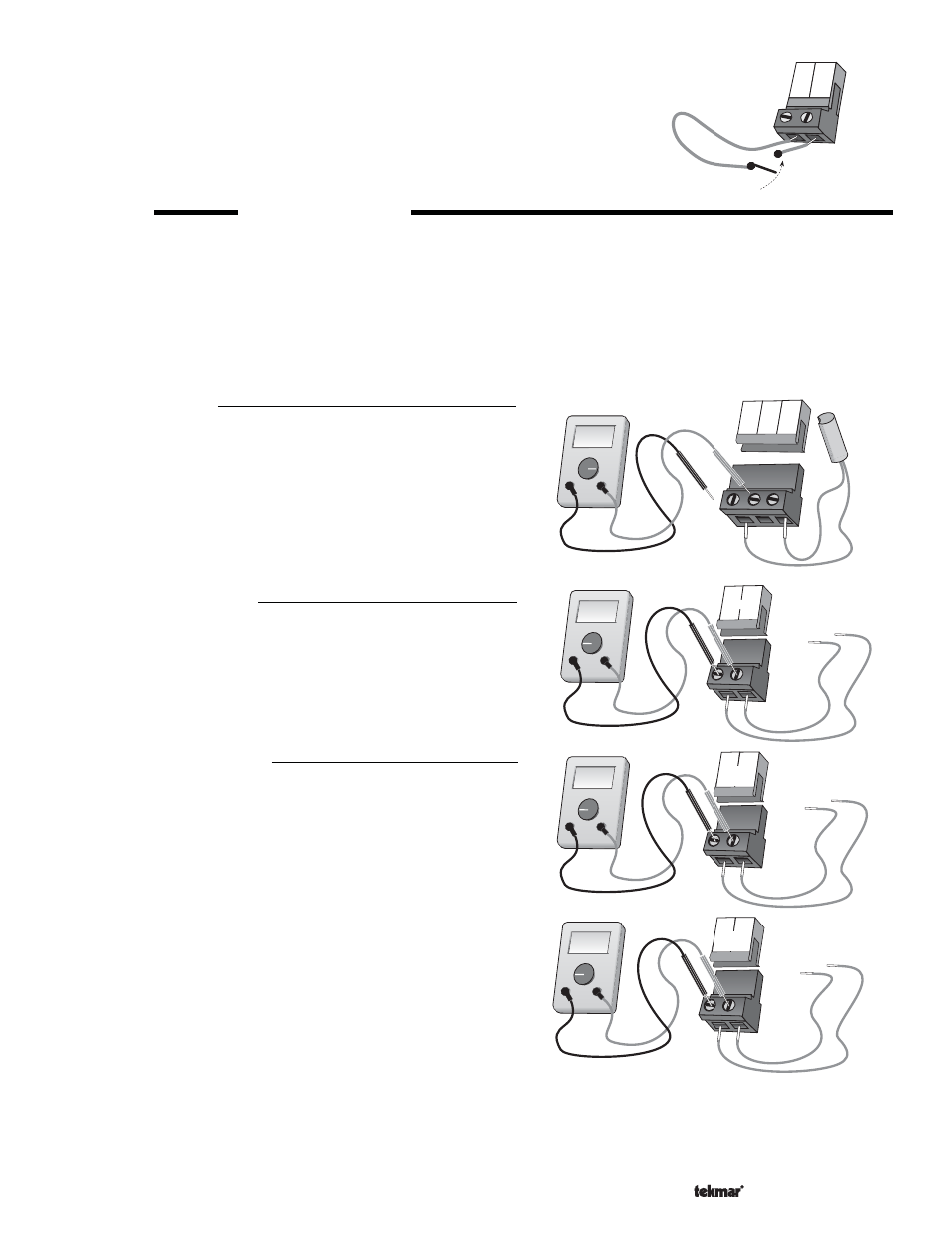
Test The Power Supply
Make sure exposed wires and bare terminals are not in contact with
other wires or grounded surfaces. Turn on the power and measure
the voltage between the
Power L and Power N terminals (5 and 6)
using an AC voltmeter. The reading should be between 108 and 132
V (ac).
Test The Powered Inputs
Boiler Demand
Measure the voltage between the
Boiler Demand terminals (1 and
2). When the boiler demand device calls for heat, you should
measure between 20 and 260 V (ac) at the terminals. When the
boiler demand device is off, you should measure less than 5 V (ac).
Setpoint Demand
If a setpoint demand is used, measure the voltage between the
Setpoint Demand terminals (3 and 4). When the setpoint demand
device calls for heat, you should measure between 20 and 260 V
(ac) at the terminals. When the setpoint demand device is off, you
should measure less than 5 V (ac).
Ω
V
V
3
4
Setpoint
Demand
20 to 260 V (ac)
Ω
V
V
1
2
Boiler
Demand
20 to 260 V (ac)
Ω
V
V
5
6
L
N
Power
108 to 132 V (ac)
Ω
Ω
V
15
Boil
Out
16
17
Com
13
Com
Timer switch
UnO
Sw
14