Dip switch settings – tekmar 261 Boiler Control User Manual
Page 12
Copyright © D 261 - 0
3/09
12 of 20
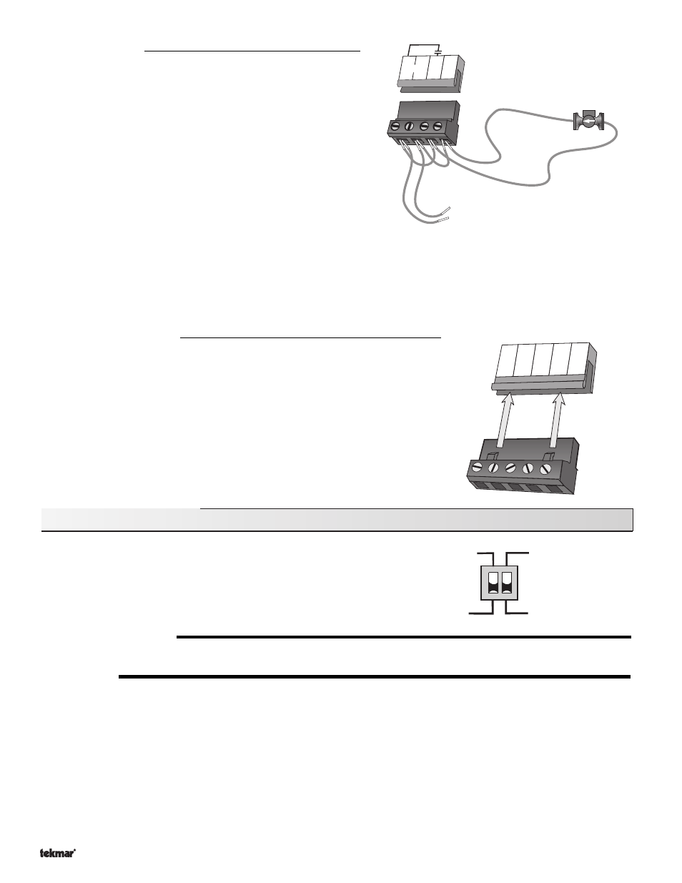
Test The Outputs
Boiler Pump (
Boil Pmp)
If the boiler pump is connected to the
Boil Pmp terminal (7), make
sure power to the terminal block is off, and install a jumper between
the
Power L and the Boil Pmp terminals (5 and 7). Install a second
jumper between
Power N and N terminals (6 and 8). When power is
applied to the
Power L and Power N terminals (5 and 6), the boiler
pump should start. If the pump does not turn on, check the wiring
between terminal block and pump, and refer to any installation or
troubleshooting information supplied with the pump. If the pump
operates properly, disconnect the power and remove the jumpers.
Stage 1 and 2
If the boiler circuit is connected to the
Stage 1 terminals (9 and 10) and / or Stage 2 terminals (11 and 12), make sure power to the
boiler circuit is off, and install a jumper between the terminals. When the boiler circuit is powered up, the boiler should fire. If the
boiler does not turn on, refer to any installation or troubleshooting information supplied with the boiler. (The boiler may have a flow
switch that prevents firing until the boiler pump is running). If the boiler operates properly, disconnect the power and remove the
jumper.
Connecting The Control
Make sure all power to the devices and terminal blocks is off, and remove any
remaining jumpers from the terminals.
Reconnect the terminal blocks to the control by carefully aligning them with their respective
headers on the control, and then pushing the terminal blocks into the headers. The
terminal blocks should snap firmly into place.
Install the supplied safety dividers between the unpowered sensor inputs and the powered
or 120 V (ac) wiring chambers.
Apply power to the control. The operation of the control on power up is described in the
Sequence of Operation section of this brochure.
DIP Switch Settings
The DIP Switch settings on the control are very important and should be
set to the appropriate settings prior to making any adjustments to the
control through the user interface. The DIP switch settings change the
items that are available to be viewed and / or adjusted in the user
interface.
ADVANCED / INSTALLER
The
Advanced / Installer DIP switch is used to select which items are available to be viewed and / or adjusted in the user interface.
ROTATE / OFF
The
Rotate / Off DIP switch enables rotation of the boiler stages based on the Equal Run Time Rotation function. This function occurs
whenever the lead boiler accumulates 48 hours more running time than the lag boiler. If a single Lo-Hi boiler is used, the DIP switch
must be set to the
Off position.
13 14 15
17
16
Uno
Sw
Com Boil Out Com
Return
Installer
Off
Rotate
Advanced
5
6
Boil
Pmp
7
8
N
Power
120 V (ac)
L
N
L
N
Boiler
pump