Step five — electrical connections to the control, Test the power supply, Test the outputs – tekmar 157 Difference Setpoint Control User Manual
Page 9: Powered input connections, Output connections, 120 v (ac) l n
9 of 16
© 2010 D 157 - 06/10
Test the Power Supply
Make sure exposed wires and bare terminals are not in
contact with other wires or grounded surfaces. Turn on
the power and measure the voltage across the 24 V (ac)
power supply with an AC voltmeter. The reading should be
between 20 and 28 V (ac).
Class 2
Transformer
L
N
R
C
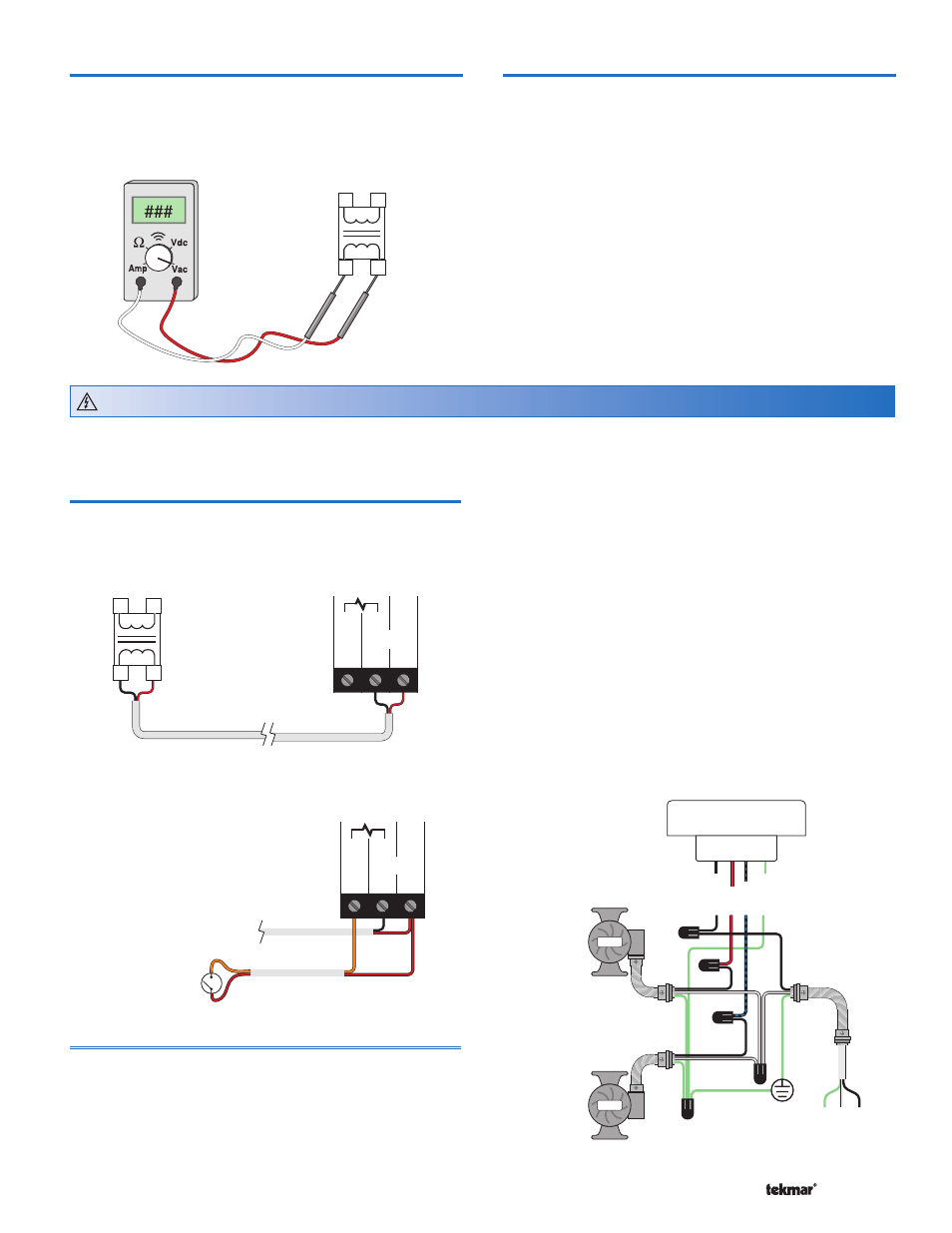
Test the Outputs
Variable Speed and Second Pump
Connect the power supply L and N directly to each pump
and use the panel breaker switch to test for 100% output.
If the pump does not operate, check the wiring and refer
to any installation or troubleshooting information supplied
with the pump. If the pump operates properly, turn off the
power at the breaker and follow wiring instructions to provide
power through the control.
Step Five — Electrical Connections to the Control
The installer should test to confirm that no voltage is present
at any of the wires.
Powered Input Connections
24 V (ac) Power
Connect the 24 V (ac) power supply to the Power C and
Power R terminals (6 and 7). This connection provides
power to the microprocessor and display of the control.
L
N
R
C
5
6
7
Power
Dem C
R
Enable / Disable Demand
To generate a demand, terminal 5 must be connected to
terminal 7 (R) through a switching device.
Demand
Switch
5
6
7
Power
Dem C
R
24 V (ac)
Output Connections
Variable Speed Pump
The 157 can vary the speed of a permanent capacitor,
impedance protected, or equivalent pump motor that has a
locked rotor current of less than 2.4A. Most small wet rotor
circulators are suitable as described in table 1. The 157
has an internal overload protection circuit which is rated at
2.5A 250V (ac). Contact your tekmar sales representative
for details on the repair procedures if this circuit is blown.
Connect one of the wires from the variable speed pump
to the blue wire at the back of the control. Connect the
black wire from the back to the live (L) side of the 120 V
(ac) power source. The other wire on the variable speed
injection pump must be connected to the neutral (N) side
of the 120 V (ac) power supply. Connect the green wire on
the back of the control to ground.
Second Pump
Connect one of the wires from the Second pump to the
red wire at the back of the control. Connect the black
wire from the back of the control to the live (L) side of the
120 V (ac) power source if not already connected. The
other wire on the Second pump must be connected to the
neutral (N) side of the 120 V (ac) power supply. Connect
the green wire on the back of the control to ground if not
already connected.
Pump
Pump
157 bottom view
Variable
Speed
Pump
(Connect
to Blue
on 157)
Second
Pump
(Connect
to Red
on 157)
120 V (ac)
L
N
Black
Red
Blue
Green
G