Sequence of operation – tekmar 157 Difference Setpoint Control User Manual
Page 4
©
2010 D
157
-
06/10
4
of
16
Sequence of Operation
Section A – General
Powering Up The Control
When the Difference Setpoint Control 157 is powered up,
all segments are displayed in the LCD for 2 seconds, and
then the type number is displayed for 2 seconds. Next,
the software version is displayed for 2 seconds. Finally,
the control enters into the normal operating mode and by
default the LCD displays the current ΔT temperature.
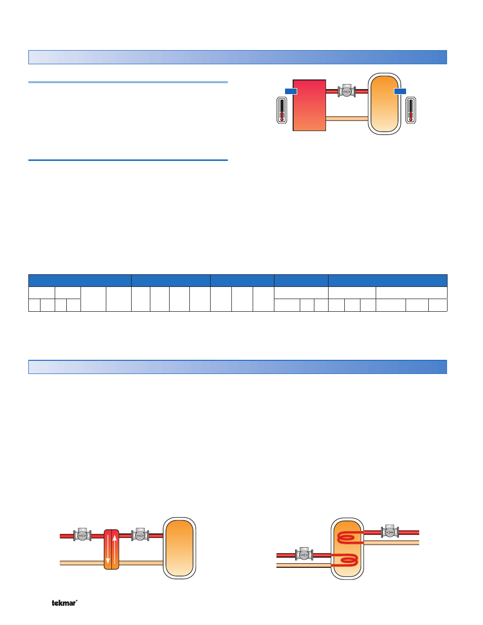
Variable Speed Pump
A manufacturer approved wet rotor circulator is connected to
the 157 at the back of the control (see Table 1 for approved
pumps). The 157 increases or decreases the power output
to the circulator to vary the speed and maintain the target
difference setpoint temperature (ΔT) between the source
and the storage sensors. As the ΔT increases, the pump
speed increases and as the ΔT decreases, the pump speed
decreases. The current % output of the variable speed
pump is displayed in the view menu.
Heat
Source
Heat
Storage
Pump
Storage
Sensor
Source
Sensor
Turn On
When the variable speed pump turns on, it will operate
at 100% output for an adjustable amount of time before
operating at a variable speed starting at the minimum
pump speed setting.
Turn Off
If the temperature difference falls below the ΔT target less
the ΔT differential, or below 1°F (0.5°C), the variable
speed pump will operate at the minimum pump speed for
2 minutes before shutting off. The minimum off time for the
variable speed pump is fixed at 2 minutes.
Table 1: Manufacturer approved pump models
Grundfos (F)
Taco
B & G
Armstrong
Wilo
15-42 15-58 26-64 43-75 003 007 0010 0012 NRF
9
NRF
22
NRF
33
Astro
Star S16FX
Star
** *** ** ***
25BU 30 50
*
**
*** S21FX 17FX 30F
*Speed 1,**Speed 2, ***Speed 3
These circulators have been tested and approved by the manufacturer for use with tekmar variable speed electronics.
The 157 has a second 120 V (ac) powered output wired
through the back of the control for an on/off pump. The
second pump has 4 adjustable modes of operation
depending on the application.
Mode Off
is for applications where the second pump is
not used. The second pump relay is non-operational. Refer
to application A157-1.
Mode 1 Heat Exchanger
is for applications where the
heat exchanger pump is needed to transfer heat between
an external heat exchanger and the storage tank. The heat
exchanger pump relay will operate whenever the variable
speed pump is above 0% output. Refer to application
A157-2.
Heat
Storage
Variable
Speed Pump
Heat Exchanger
Pump
Mode 2 Heat Supplement
is for applications where the
heat supplement pump transfers heat from a supplemental
heat source (i.e. back-up boiler) to maintain the storage tank
above the minimum storage target. The auxiliary sensor is
optional in this mode. Install the auxiliary sensor in the upper
portion of the storage tank. Refer to application A157-3.
If the boiler is not flow activated, the heat supplement pump
output could provide a heat demand to another controller
to turn on the boiler.
In this mode, the minimum on and off time for the heat
supplement pump is fixed at 30 seconds.
Heat
Storage
Variable
Speed Pump
Supplemental
Heat Pump
Section B – Modes of Operation