Aileron servo installation – E-flite Twist 3D 480 ARF User Manual
Page 5
5
E-flite Twist 3D 480 ARF Assembly Manual
During the course of building your model, we
suggest you use a soft base for the building surface.
Such things as a foam stand, large piece of
bedding foam or a thick bath towel will work well
and help protect the model from damage during
assembly. This is not shown in the instructions
to provide the greatest detail in the photos.
When referencing directions (up, down, left,
right top and bottom), these directions are in
relationship to the pilot sitting in the cockpit
of the aircraft, unless noted otherwise.
Before starting the assembly of your model, we
recommend preparing your radio system for
installation. This includes charging the transmitter and
receiver batteries, as well as centering the trims and
sticks on your transmitter. If using a computer radio,
make sure to reset a model memory and name it for
this particular model. We also recommend binding
the transmitter and receiver at this time, following
the instructions provided with your radio system.
We highly recommend re-binding the radio
system once all the control throws are set. This will
keep the servos from moving to their endpoints
until the transmitter and receiver connect.
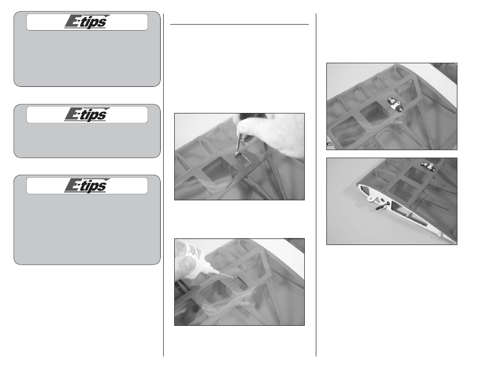
Aileron Servo Installation
Required parts
Wing panel (right and left)
Servo with hardware (2)
Required Tools and Adhesives
Thin CA
Phillips screwdriver: #1
1. Use a #1 Phillips screwdriver to thread a
servo mounting screw into each of the holes to
cut threads in the surrounding wood. Remove the
screw before moving to the next step.
2. Apply 1–2 drops of thin CA in each of the holes
to harden the surrounding wood. This will prevent
the screws from stripping surrounding wood.
3. Insert the servo lead into the wing. Hold the
wing with the tip in the air and guide the lead out
of the wing at the wing root. Secure the servo in
the wing using the screws provided with the servo
and a #1 Phillips screwdriver. The output shaft of
the servo faces toward the aileron as shown.
4. Repeat steps 1 through 3 to install the remaining
aileron servo.