Rudder and elevator servo installation – E-flite Twist 3D 480 ARF User Manual
Page 17
17
E-flite Twist 3D 480 ARF Assembly Manual
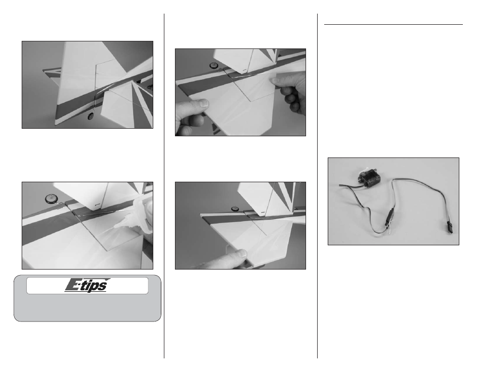
12. Slide the rudder into position, guiding the tab
on the tail wheel knuckle into the slot at the bottom
of the rudder.
13. Check to make sure the counterbalance can
move freely without hitting the top of the fin.
Remove the t-pins from the hinges and apply
thin CA to each of the hinges. Make sure to fully
saturate both sides of the hinges.
Do not use CA accelerator when gluing the hinges.
The CA must be allowed to soak into the hinge for the
best bond between the hinge and surrounding wood.
14. Once the CA has cured, gently pull on the
control surfaces and fin to make sure the hinges
are glued securely. If not, apply CA to those hinges
that are not glued and recheck.
15. Move the rudder through its range of motion
a number of times to break in the hinges. This will
reduce the initial load on the servo when the servo
is connected for the first time.
Rudder and Elevator Servo Installation
Required parts
Fuselage
Servo with hardware (2)
Flight battery
Pushrod connector (2)
Transmitter
9-inch (228mm) servo extension (2)
Nylon control horn with backplate (2)
2.0mm x 170mm pushrod with Z-bend (2)
Required Tools and Adhesives
Medium CA
Thin CA
Side cutters
String or dental floss
Hex wrench: 1.5mm
Pin vise
Phillips screwdriver: #0, #1
Drill bit: 5/64-inch (2mm)
1. Use string or dental floss to secure a 9-inch
(228mm) servo extension to one of the servos.