U-gage, T30 series with analog and discrete outputs, Run mode – Banner U-GAGE T30U—Level Control User Manual
Page 5: Analog output, Self-diagnostic error mode
U-GAGE
™
T30 Series with Analog and Discrete Outputs
P/N 57438 Rev. C
5
Banner Engineering Corp.
•
Minneapolis, MN U.S.A.
www.bannerengineering.com • Tel: 763.544.3164
RUN Mode
NOTE: All LED indicators momentarily go OFF when sensor changes state between
PROGRAM and RUN modes.
Signal LED
The red Signal LED indicates the strength and condition of the sensor’s incoming
signal.
Signal LED Status
Indicates
OFF
No signal is received, or the target is beyond the range limitations
of the sensor (with some tolerance beyond the recommended
minimum and maximum sensing distance)
Flashing
Relative received signal strength
Power ON/OFF LED
Indicates
OFF
Power is OFF (or in PROGRAM mode, if other LEDs are ON)
ON Solid
Sensor is operating normally (power is ON, RUN mode)
Output LEDs
Each yellow Output LED lights when a target is sensed within the programmed window
limits.
Power ON/OFF LED
The green Power ON/OFF LED indicates the operating status of the sensor.
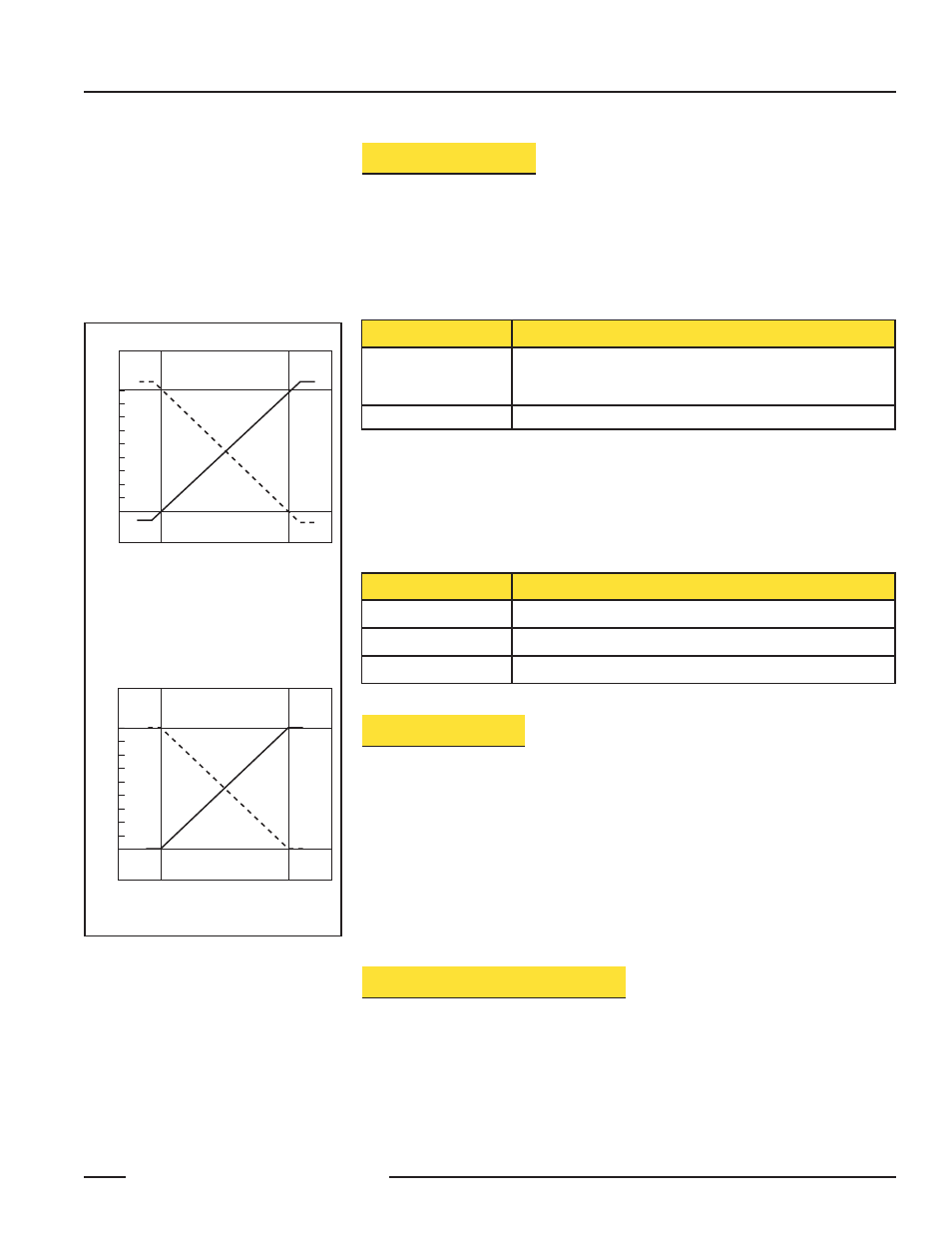
Analog Output
The U-GAGE T30 Series sensor may be programmed for either a positive or a negative
output slope, based on which condition is taught first (see Figure 3). If the near limit is
taught first, the slope will be positive; if the far limit is taught first, the slope will be
negative. Banner’s scalable analog output automatically distributes the output signal over
the width of the programmed sensing window.
The U-GAGE T30 also features a 2-second hold upon loss of the analog signal, which is
useful for harsh and unstable applications. In the event of analog signal loss for longer
than 2 seconds, the analog output goes to 3.6 mA or 0V dc, which may be used to trigger
an alarm.
Self-Diagnostic Error Mode
In the unlikely event of a microprocessor memory error, all of the LEDs will flash in
sequence. If this occurs, the setup parameters have been lost and the sensor may be
corrupt. Contact your Banner representative for further information.
0
Near
Window
Far
Window
10
Target Position
Analog Output (V dc)
Positive
Slope
Voltage-Sourcing Models
Figure 3.
Output current as a function of
target position
NOTE: The analog current output tracks
slightly past each window limit
(from 3.8 to 20.5 mA).
4
Near
Window
Far
Window
20
Target Position
Analog Output (mA)
Positive
Slope
Current-Sourcing Models
Flashing
Discrete output is overloaded (RUN mode)