7 gain configuration, Overview – Banner EZ-ARRAY USB Serial Adapter User Manual
Page 9
P/N 130426 Rev. C
7
Banner Engineering Corp.
•
Minneapolis, U.S.A.
www.bannerengineering.com • Tel: 763.544.3164
A-GAGE EZ-ARRAY
Instruction Manual
Overview
1.7 Gain Configuration
The EZ-ARRAY provides two gain options for straight scan
applications: high excess gain and low contrast. The gain
method can be selected using the receiver push button, the
receiver remote teach wire, or the PC interface.
High (maximized) excess gain is suited for detecting opaque
objects and for reliable sensing in dirtier environments where
objects to be detected are 10 mm or larger. The high excess
gain method is always used in single- and double-edge scan.
The high excess gain option has a minimum blocked threshold
level, which provides reliable sensing at higher excess gain
levels.
The low-contrast setting is used for sensing semi-transparent
materials and for detecting objects as small as 5 mm (straight
scan only). In low-contrast operation, only a portion of a beam
must be blocked for detection to occur. In low-contrast operation,
the sensor sets an individual threshold for each optical channel
during the alignment process; this process equalizes the signal
strength to allow semi-transparent object detection.
When using the PC interface, low-contrast sensing provides
a fine-tune sensitivity setting of 15% to 50%. When using the
receiver interface, low-contrast sensitivity is always 30%.
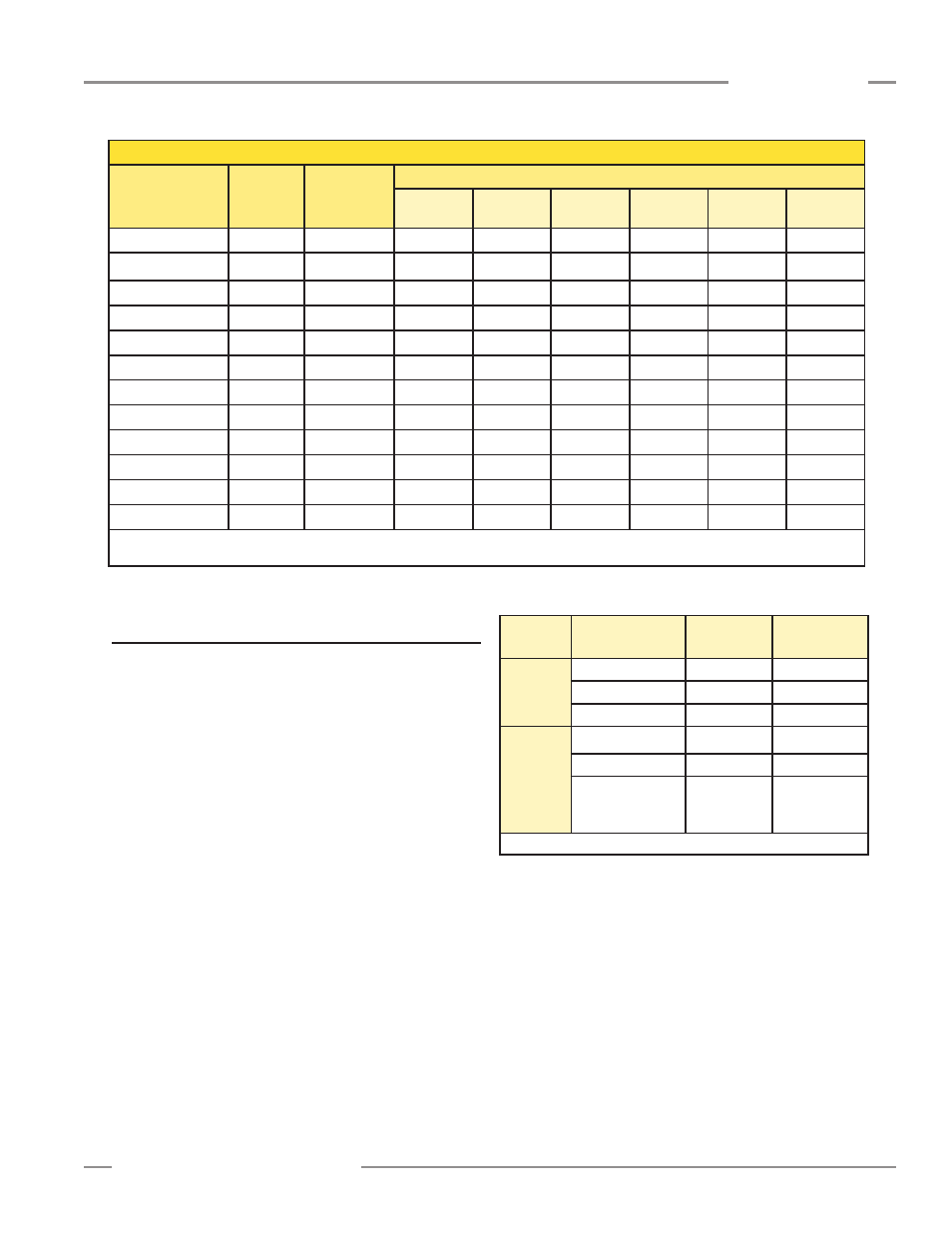
Gain
Setting
Scan Method
EZ-ARRAY
MODS*
EZ-ARRAY
Resolution
Low
Contrast
Straight scan
5 mm
5 mm
Single-edge scan
—
—
Double-edge scan
—
—
High
Excess
Gain
Straight scan
10 mm
5 mm
Single-edge scan
10 mm
2.5 mm
Double-edge scan
Depends on
step size
2.5 mm / edge
5 mm total
(both edges)
* MODS: Minimum Object Detection Size
Figure 1-9. Effects of Gain selection on minimum object detection
size and sensing resolution
Maximum Scan Times (in milliseconds)
Array Length
Straight
Scan
Single-Edge
Scan
Double-Edge Scan
Step
1 Beam
Step
2 Beams
Step
4 Beams
Step
8 Beams
Step
16 Beams
Step
32 Beams
150 mm (5.9")
2.8
1.5
3.4
2.8
2.5
2.4
1.9
N/A
300 mm (11.8")
5.0
1.5
5.9
4.1
3.2
2.8
2.3
2.1
450 mm (17.7")
7.1
1.6
8.5
5.5
4.2
4.0
3.2
2.5
600 mm (23.6")
9.3
1.6
11.0
6.8
4.9
4.2
4.0
2.8
750 mm (29.5")
11.4
1.7
13.5
8.1
5.7
4.6
4.5
4.5
900 mm (35.4")
13.6
1.7
16.0
9.5
6.1
4.7
4.6
4.6
1050 mm (41.3")
15.7
1.8
18.6
10.8
6.8
5.2
4.8
4.8
1200 mm (47.2")
17.9
1.8
21.1
12.2
7.4
5.5
4.9
4.9
1500 mm (59.1")
22.2
1.9
26.1
14.8
9.0
6.4
5.3
4.9
1800 mm (70.9")
26.5
2.0
31.2
17.5
10.5
7.3
6.0
5.6
2100 mm (82.7")
30.8
2.8
36.3
20.2
12.0
8.2
6.7
5.6
2400 mm (94.5")
35.1
2.8
41.4
22.9
13.5
9.1
7.4
5.9
NOTES: Scan times are exclusive of serial communication transmission times.
Scan times are also dependent on analog filter speed; see Section 5.8.
Figure 1-8. Maximum scan times for straight, single-edge and double-edge scanning