Appendix, A.3 input registers – Banner EZ-ARRAY USB Serial Adapter User Manual
Page 42
40
P/N 130426 Rev. C
Banner Engineering Corp.
•
Minneapolis, U.S.A.
www.bannerengineering.com • Tel: 763.544.3164
A-GAGE EZ-ARRAY
Instruction Manual
Appendix
Table A–28. Scan Response (Discrete Outputs 1 and 2)
Range
Description
1-250
Number of consecutive measurements before
changing state
Table A–29. Hysteresis LOW (Discrete Outputs 1 and 2)
Range
Description
0-479
Lower hysteresis threshold for discrete output
(MUST be < Threshold LOW)
Table A–30. Hysteresis HIGH (Discrete Outputs 1 and 2)
Range
Description
2-481
Upper hysteresis threshold for discrete output
(MUST be > Threshold HIGH)
Table A–31. Threshold LOW (Discrete Outputs 1 and 2)
Range
Description
1-480
Lower threshold for discrete output
(MUST be <= Threshold HIGH)
Table A–32. Threshold HIGH (Discrete Outputs 1 and 2)
Range
Description
1-480
Upper threshold for discrete output
(MUST be >= Threshold LOW)
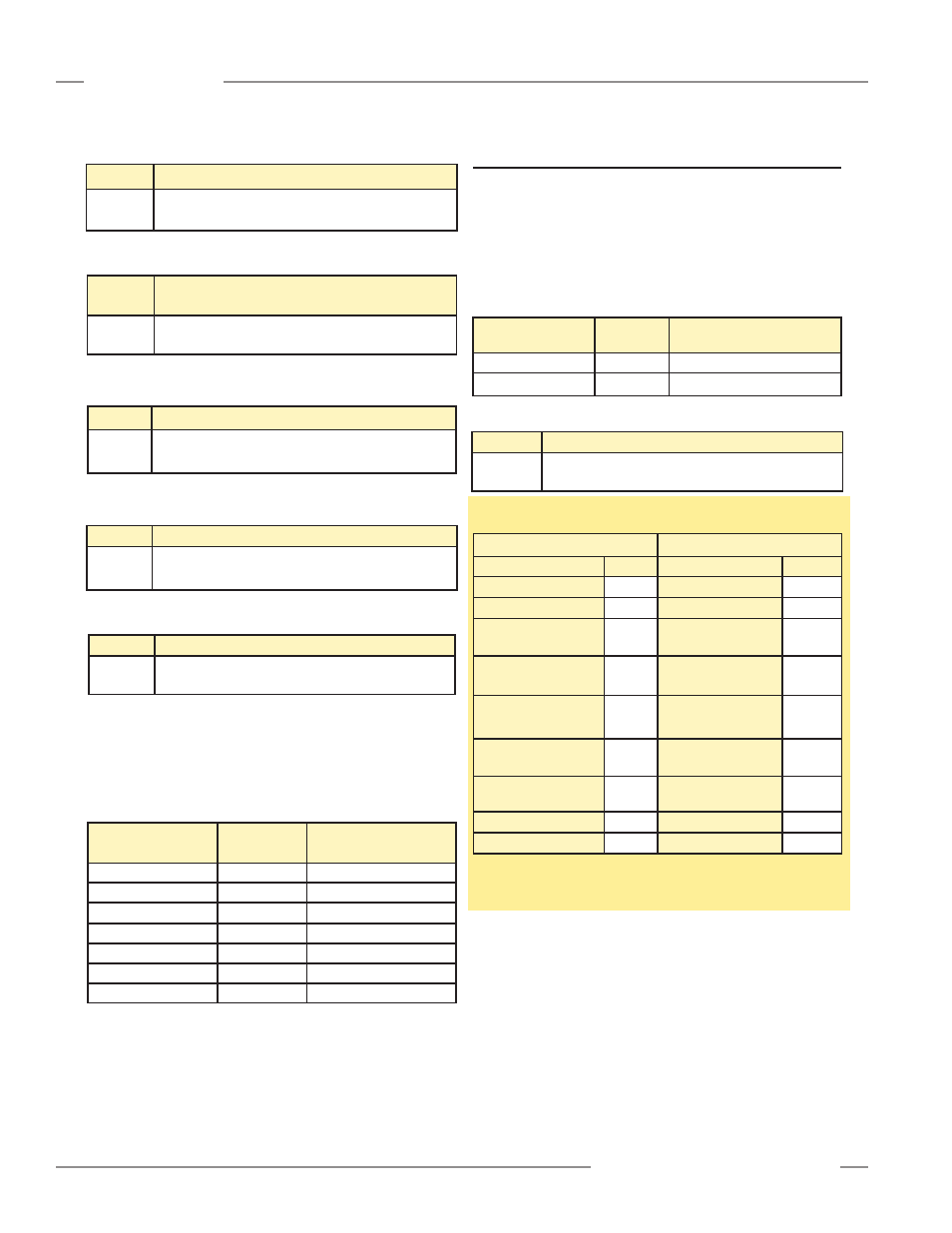
Discrete Output 2 Configuration
The Discrete Output 2 Configuration contains the settings for the
second discrete output.
Table A–33. Discrete Output 2 Configuration
Holding Register
Address
MASK
Member Name
40040
LOW BYTE
Config
40040
HIGH BYTE
RESERVED
40041
Demodulation Count
40042
Hysteresis LOW
40043
Hysteresis HIGH
40044
Threshold LOW
40045
Threshold HIGH
A.3 Input Registers
A.3.1 Active Measurements
The Active Measurements section contains the current values
of the two measurements that were configured in the General
Configuration. The Active Measurements data can be read after
each scan.
Table A–34. Active Measurements
Input Register
Address
MASK
Member Name
30001
Measurement 1
30002
Measurement 2
Table A–35. Measurement 1 and Measurement 2
Range
Description
0-1920
Measurements are represented in 4x channel
resolution
Example A–5. Reading Active Measurements
Request
Response
Field Name
(Hex)
Field Name
(Hex)
Slave Address
41
Slave Address
41
Function
04
Function
04
Starting Address
(HIGH Byte)
75
Byte Count
04
Starting Address
(LOW Byte)
31
Register 30001
(HIGH Byte)
00
Quantity of Registers
(HIGH Byte)
00
Register 30001
(LOW Byte)
20
Quantity of Registers
(LOW Byte)
02
Register 30002
(HIGH Byte)
00
CRC (LOW Byte)
34
Register 30002
(LOW Byte)
90
CRC (HIGH Byte)
C8
CRC (LOW Byte)
BB
CRC (HIGH Byte)
E6
To read the Active Measurements, a read input registers request
is sent starting at address 30001, requesting 2 registers.