Pc interface, A-gage ez-array – Banner EZ-ARRAY USB Serial Adapter User Manual
Page 35
P/N 130426 Rev. C
33
Banner Engineering Corp.
•
Minneapolis, U.S.A.
www.bannerengineering.com • Tel: 763.544.3164
A-GAGE EZ-ARRAY
Instruction Manual
PC Interface
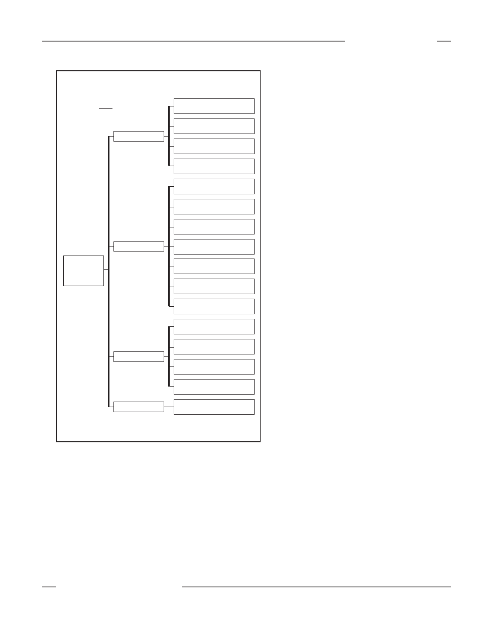
Sensor > Setup (Ctrl + S) > System Diagnostics View*
(Not available until Connect is performed)
* Use drop-down arrow at right-hand side of the
Current View
field to quickly move to another view.
F
Channel Status
Number of Receiver Channels
Read-only indication
Number of Emitter Channels
Read-only indication
First Bad Emitter Channel
Read-only indication
Emitter Power
Read-only indication
Error Code
Read-only indication
DIP Switch S1
Read-only indication
DIP Switch S2
Read-only indication
DIP Switch S3
Read-only indication
DIP Switch S4
Read-only indication
DIP Switch S5
Read-only indication
DIP Switch S6
Read-only indication
Output Status
Service Status
Discrete Output 1
Read-only indication
Discrete Output 2
Read-only indication
Analog Output 1 DAC
Read-only indication
Analog Output 2 DAC
Read-only indication
Time of Service (Hours)
Read-only indication
Operational Status
F
Diagnostics
NOTE: Underlined options
designate default settings.
Figure 5-12. PC Interface configuration overview, part 7 of 7