Appendix, Request, Response – Banner EZ-ARRAY USB Serial Adapter User Manual
Page 37: Error, Example a–2. reading input registers, Example a–3. writing holding registers
P/N 130426 Rev. C
35
Banner Engineering Corp.
•
Minneapolis, U.S.A.
www.bannerengineering.com • Tel: 763.544.3164
A-GAGE EZ-ARRAY
Instruction Manual
Appendix
Request
Function Code
1 byte
0x04
Starting Address
2 bytes
0x0000 to 0xFFFF
Quantity of Input
Registers
2 bytes
0x0001 to 0x007D
Response
Function Code
1 byte
0x04
Byte Count
1 byte
2 X N*
Input Registers
N X 2 Bytes
* “N” is the number of holding registers
Error
Error Code
1 byte
0x84
Exception Code
1 byte
1 to 4
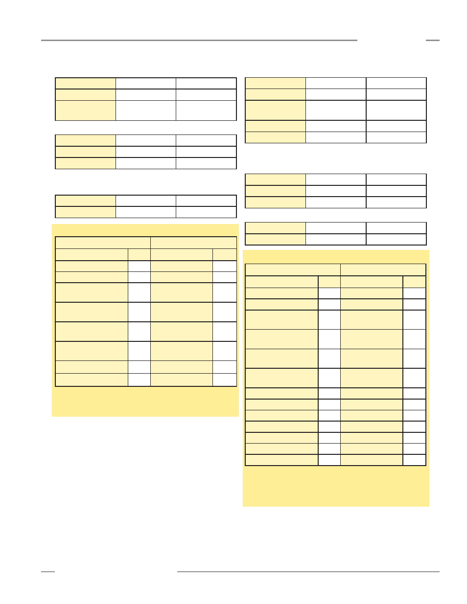
Example A–2. Reading Input Registers
Request
Response
Field Name
(Hex)
Field Name
(Hex)
Slave Address
41
Slave Address
41
Function
04
Function
04
Starting Address (HIGH
Byte)
75
Byte Count
02
Starting Address (LOW
Byte)
31
Register8
(HIGH Byte)
00
Quantity of Registers
(HIGH Byte)
00
Register8
(LOW Byte)
2B
Quantity of Registers
(LOW Byte)
01
CRC (LOW Byte)
38
CRC (LOW Byte)
74
CRC (HIGH Byte)
F8
CRC (HIGH Byte)
C9
The contents of address 30001 are shown as the two-byte
values of 0x000A (10 decimal).
A.1.3 Write Multiple Holding Registers (0x10)
This function code is used to write a block of contiguous
registers into the EZ-ARRAY. The requested written values are
specified in the request data field. The EZ-ARRAY employs a
direct addressing scheme. For example, the holding register at
address 40001 is accessed by writing address 40001 (0x9C41)
directly (i.e. the starting address is not an offset). Data is packed
as two bytes per register. For each register, the data is sent in
big endian order (HIGH byte, LOW byte). The normal response
returns the function code, starting address, and quantity of
registers written.
Request
Function Code
1 byte
0x10
Starting Address
2 bytes
0x0000 to 0xFFFF
Quantity of
Holding Registers
2 bytes
0x0001 to 0x007B
Byte Count
1 byte
2 X N*
Register Value
* “N” is the number of holding registers
Response
Function Code
1 byte
0x03
Starting Address
2 bytes
0x0000 to 0xFFFF
Holding Registers
N X 2 Bytes
1 to 0x7B
Error
Error Code
1 byte
0x90
Exception Code
1 byte
1 to 4
Example A–3. Writing Holding Registers
Request
Response
Field Name
(Hex)
Field Name
(Hex)
Slave Address
41
Slave Address
41
Function
10
Function
10
Starting Address
(HIGH Byte)
9C
Starting Address
(HIGH Byte)
9C
Starting Address
(LOW Byte)
41
Starting Address
(LOW Byte)
41
Quantity of Registers
(HIGH Byte)
00
Quantity of Registers
(HIGH Byte)
00
Quantity of Registers
(LOW Byte)
02
Quantity of Registers
(LOW Byte)
02
Byte Count
04
CRC (LOW Byte)
31
Register 1 (HIGH Byte)
00
CRC (HIGH Byte)
4C
Register 1 (LOW Byte)
01
Register 2 (HIGH Byte)
0A
Register 2 (LOW Byte)
02
CRC (LOW Byte)
3A
CRC (HIGH Byte)
C7
The holding registers at addresses 40001 and 40002, were
written to the two-byte values of 0x000A (10 decimal) and
0x0102 (258 decimal), respectively.