Overview, 2 features, 3 configuration via dip switch or pc interface – Banner EZ-ARRAY USB Serial Adapter User Manual
Page 4
2
P/N 130426 Rev. C
Banner Engineering Corp.
•
Minneapolis, U.S.A.
www.bannerengineering.com • Tel: 763.544.3164
A-GAGE EZ-ARRAY
Instruction Manual
Overview
1.2 Features
Built-in features in the EZ-ARRAY contribute to its ease of
use. Many features are available using either the user-friendly
receiver interface or the more advanced PC interface.
Built-in diagnostic programming and easy-to-see indicators on
the receiver simplify physical alignment and troubleshooting
(Figure 1-3); more advanced diagnostics are available via the
PC interface.
The receiver has a bright LED that indicates overall sensing
status (OK, marginal alignment, and hardware error). Two
other LEDs indicate serial communication status. Seven Zone
indicators each communicate the blocked / aligned status of one-
seventh of the total array. A 3-digit diagnostic display provides
further diagnostic information, including number of beams
blocked, whether blanking is configured, and troubleshooting
codes.
The emitter has a red LED that signals proper operation (ON
when power is applied). See Section 1.4 for more information
about indicators and Section 4.5 for display codes and
troubleshooting.
The Alignment routine (Section 4.2 or Section 5.6) automatically
equalizes the excess gain of each beam for reliable object
detection throughout the array. This routine need not be
performed again unless the sensing application changes, or if
the emitter and/or receiver is moved.
Configurable beam blanking accommodates machine
components and fixtures that must remain in or move through the
light screen. Blanking may be set using the receiver interface,
the teach wire, or the PC interface.
The EZ-ARRAY light screen provides a wide selection of sensing
and output options, including measurement (“scan analysis”)
modes and scanning methods that can determine a target
object’s location, overall size, total height, or total width, or the
number of objects. Scanning may be continuous or controlled by
a gate sensor. Up to 15 systems may be networked, via Modbus;
see Section 5 and Appendix A.
1.3 Configuration via DIP Switch or PC Interface
Commonly used configuration options can be set up easily via
a six-position DIP switch located behind a hinged clear access
panel on the front of the receiver.
Access to the DIP switch can be prevented by using the screw-
on security plate to hold the clear access panel closed or by
disabling them via the PC interface.
For more advanced, individualized applications, use the supplied
PC interface software program (the “Banner Sensors GUI”;
Section 5) to configure the receiver. The menu-driven program
easily accesses the many scanning and output options. After
the desired options are selected, the combination of selections
can be saved in an .xml file, stored in the system configuration
computer, and recalled as needed. Communication between the
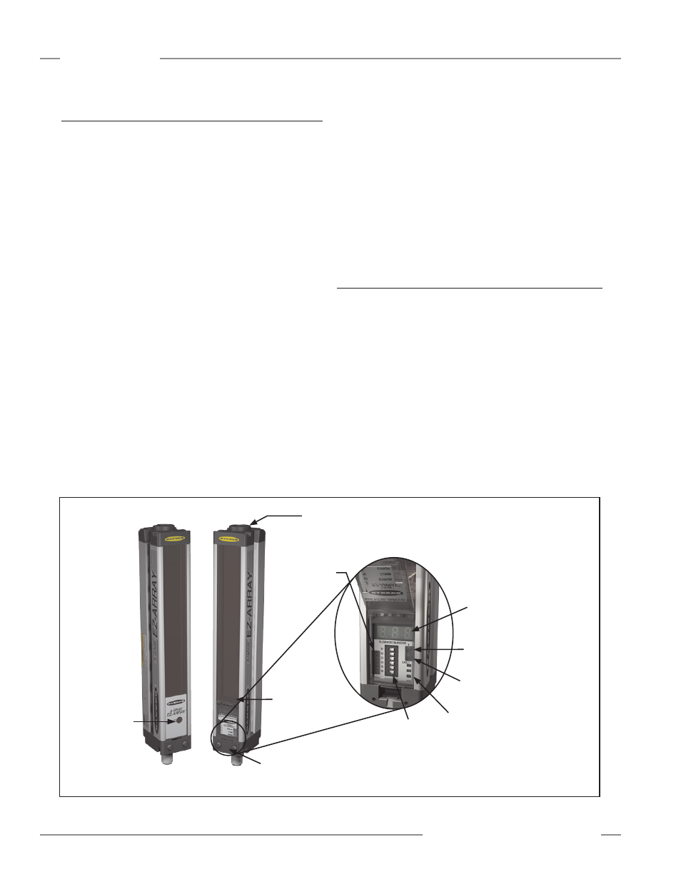
Figure 1-3. A-GAGE EZ-ARRAY features
Beam #1
(Closest to
Display)
Power ON
LED
Emitter
Receiver
3-Digit Diagnostic
Display
Screw-on Security Plate
limits access to DIP switch
and push buttons
Zone Indicators
Gain (Sensitivity Adjust)
Push Button
6-Position
Configuration
DIP Switch
Alignment/Blanking
Push Button
Connection to 5-pin
Communication Cable
Under Hinged Access Panel:
Status, Communication Active, and
Communication Error LEDs