2 system features, System description, Din-rail-mountable control module – Banner A-GAGE MINI-ARRAY Series User Manual
Page 6
System Description
6
Banner Engineering Corp. • Minneapolis, U.S.A.
Website: http://www.baneng.com • Tel: 888.373.6767
1.2 System Features
Built-in features simplify the operation of the A-GAGE MINI-ARRAY System. Emitters and
receivers, available in a choice of two resolutions and 10 lengths, provide the right size
and precision needed for many applications. Programmable beam blanking
accommodates machine components or other fixtures that must remain in or move
through the light screen. Blanking is set using the included EDS file and the user’s
DeviceNet configuration tool.
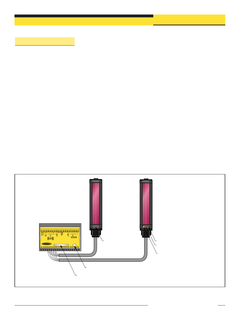
Built-in diagnostic programming and easy-to-see indicators on the sensors and the
control module simplify alignment and troubleshooting (Figure 1-2). The emitter has a
red LED that signals proper operation. The receiver has three bright LEDs: green
signals that the sensors are properly aligned; yellow signals marginal alignment; and
red signals misalignment or a blocked condition. The control module has seven
System Status LEDs that indicate conditions such as output(s) conducting, Gate signal
received, beam alignment and/or blocked beams. In addition, a bi-color (red/green)
Network Status LED indicates whether the system is online with the DeviceNet network
and whether there are problems.
The A-GAGE MINI-ARRAY System provides a wide selection of sensing and output
options, including: measurement (“scan analysis”) modes; scanning methods that can
determine the target object’s location, overall size, total height or total width; and
numerous output options. Scanning may be continuous or controlled by a host
process controller or a gate sensor.
Blanking feature allows the user to configure any number of beams to be “blanked.” In
effect, blanking causes the affected beams to be made “blind” to activity within the
array.
Figure 1-2. A-GAGE MINI-ARRAY with DeviceNet System features
DIN-Rail-Mountable Control Module
MINI-ARRAY CONTROLLER for DeviceNet
POWER
MACNXDN1
NETWORK
STATUS
1
1
V+
16 - 30V dc
1.2A MAX
EMTR
RCVR
+12V
BR
BU
BK
5 Wires
30V
150mA Max
OUT1
10-30V dc
GATE
30V
150mA Max
ALARM
WH
NC
+
–
NC
COM DRN
T/R
2 3 4 5 6 7 8 9 10 11 12 13 14 15 D5 D4 D3 D2 D1
V-
F1
T/R
V+
BR
BU
BK
5 Wires
WH
CAN_H SHIELD
V-
CAN_L
D
IA
G
1
D
IA
G
2
D
IA
G
3
O
U
T1
A
LA
RM
G
AT
E
A
LI
G
N
2
3
4
5
6
7
8
9
10
11
12
13
14
15
16
17
18
19
20
Red
Operational
LED
Network Status Indicator
Green Blocked LED
Red Marginal
Alignment LED
Yellow
Alignment LED
Diagnostic/Status Indicators
(see Section 5.1)