1 diagnostics/status indicators, System diagnostics – Banner A-GAGE MINI-ARRAY Series User Manual
Page 23
System Diagnostics
23
Banner Engineering Corp. • Minneapolis, U.S.A.
Website: http://www.baneng.com • Tel: 888.373.6767
5. System Diagnostics
System diagnostics may be performed using the status and diagnostics indicators on the
control module and sensors.
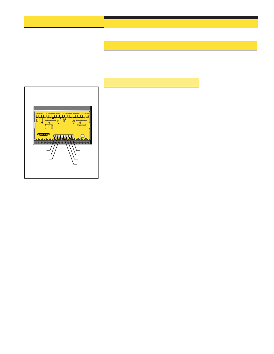
5.1 Diagnostics/Status Indicators
NOTE: Status indicators appear to “freeze” if the controller is configured for Gate or Host
mode (Section 4.4), and no signal is present to cause a scan update.
Bright, easy-to-see LED indicators on both sensors and on the front panel of the
control module provide an ongoing display of the system’s operating status.
Control Module:
Output (steady red) indicates Output #1 energized.
Alarm (flashing red) indicates Output #2 energized. This output may be assigned to an
analysis mode, or it may be used as a System Diagnostics alarm or as a Trigger alarm
to gate another A-GAGE MINI-ARRAY System.
Gate (steady red) displays the status of the Gate input.
Alignment: (steady green) indicates proper emitter/receiver alignment and a clear,
unblocked light screen. This indicator is ON when either the green or both the green
and yellow LEDs of the receiver are ON.
Diag 1, Diag 2, Diag 3: These three Diagnostics indicators are used in combination to
determine System status, as shown in the following table.
Diag 1 (Green) Diag 2 (Red) Diag 3 (Red)
Condition
ON
OFF
OFF
Normal operation
ON
ON
OFF
Receiver error
ON
OFF
ON
Emitter error
ON
ON
ON
Emitter/receiver mismatch
OFF
ON
OFF
Controller error
OFF
OFF
ON
EEPROM error
OFF
ON
ON
ROM/RAM error
Network Status Indicator: Bi-colored (red/green) LED indicates network status.
Steady Green
Online, connected to Master.
Flashing Green On-line, address and baud rate OK
Steady Red
Critical network fault or duplicate node address detected
Flashing Red
Connection timeout
OFF
No network power, or offline
Emitter:
Operational (steady red) LED indicates power to the emitter is ON.
Receiver:
Blocked (steady red) LED indicates some of the array beams are blocked.
Marginal (steady yellow) LED indicates that array alignment is marginal.
Alignment: (steady green) LED indicates that array alignment is satisfactory.
MINI-ARRAY CONTROLLER for DeviceNet
POWER
MACNXDN1
NETWORK
STATUS
1
1
V+
16 - 30V dc
1.2A MAX
EMTR
RCVR
+12V
BR
BU
BK
5 Wires
30V
150mA Max
OUT1
10-30V dc
GATE
30V
150mA Max
ALARM
WH
NC
+
–
NC
COM DRN
T/R
2 3 4 5 6 7 8 9 10 11 12 13 14 15 D5 D4 D3 D2 D1
V-
F1
T/R
V+
BR
BU
BK
5 Wires
WH
CAN_H SHIELD
V-
CAN_L
D
IA
G
1
D
IA
G
2
D
IA
G
3
O
U
T1
A
LA
RM
G
AT
E
A
LI
G
N
2
3
4
5
6
7
8
9
10
11
12
13
14
15
16
17
18
19
20
Align
Diag1
Diag2
Diag3
Gate
Alarm
Out1
Figure 5-1. A-GAGE MINI-ARRAY with
DeviceNet System diagnostics
and status indicators