2 control module mounting, Installation and mechanical alignment – Banner A-GAGE MINI-ARRAY Series User Manual
Page 15
Installation and Mechanical Alignment
15
Banner Engineering Corp. • Minneapolis, U.S.A.
Website: http://www.baneng.com • Tel: 888.373.6767
Mount the emitter and receiver in their brackets and position the red lenses of the two
units so they directly face each other. The connector ends of both sensors must point
in the same direction. Measure from one or more reference planes (e.g. the building
floor) to the same point(s) on the emitter and receiver to verify their mechanical
alignment. If the sensors are positioned exactly vertical or horizontal to the floor, a
carpenter’s level is useful for checking alignment. A straightedge or a string extended
between the sensors also helps with positioning. Also check “by eye” for line-of-sight
alignment. Make any necessary final mechanical adjustments, and hand-tighten the
bracket hardware. See Section 4.2 for further information on alignment.
3.2 Control Module Mounting
The control module must be installed inside an enclosure which has a NEMA (or IEC)
rating suitable for the operating environment.
Mounting dimensions for the controller are shown in Figure 2-2, on page 11
.
The
control module is supplied with M3.5 hardware for direct mounting to a surface, or it
may mount directly onto standard 35 mm DIN rail.
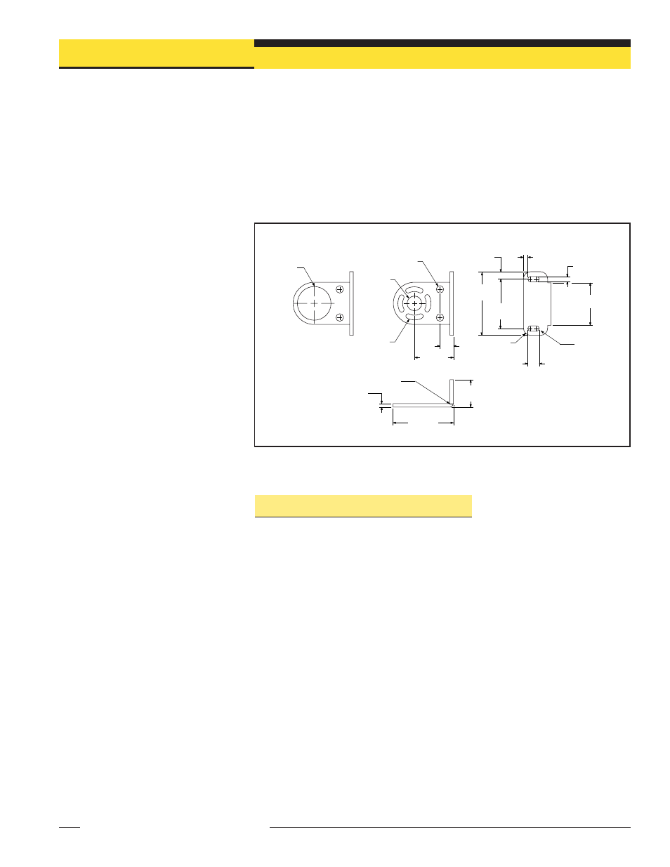
NON-QD End
QD End
Min. R.
Full R (4)
4.8 mm (2)
(0.19")
38.1 mm
(1.50")
6.4 mm R
(0.25")
44.5 mm
(1.75")
6.4 mm
(0.25")
57.2 mm
(2.25")
3.8 mm
(0.15")
10.2 mm (2)
(0.40")
ø30.5 mm
(1.20")
34.8 mm
(1.37")
11.9 mm
(0.47")
Slots have clearance
for M4 bolts (supplied)
and allow ±30° rotation
ø13.2 mm
(0.52")
ø6.8 mm (2)
(0.27")
3.0 mm
(0.12")
24.6 mm
(0.97")
53.8 mm
(2.12")
Material: Cold Rolled Steel
Finish: Black, Zinc Plated
Chromate Dip
Figure 3-2. A-GAGE MINI-ARRAY emitter and receiver mounting bracket dimensions