Sensor programming, L-gage® lt7 long-range time-of-flight sensor – Banner L-GAGE LT7 Series User Manual
Page 5
P/N 120244 Rev. B
5
Banner Engineering Corp. • Minneapolis, MN U.S.A
www.bannerengineering.com • Tel: 763.544.3164
L-GAGE® LT7 Long-Range Time-of-Flight Sensor
Sensor Programming
The sensor may be programmed using either the on-board push buttons along with the
sensor’s LCD display, or via a serial interface. For serial interface instructions, see page
14. Sensor TEACH-mode instructions follow.
From Run mode, press Enter
ESC
to access Programming mode. If Password is set to
OFF (factory setting), the sensor will proceed to the Main menu (see Figure 7). When the
sensor enters Programming mode, several things occur:
• Sensor display lights up.
• Visible red Pilot laser turns ON.
• Measurement laser remains ON, alternating with the Pilot laser.
• Sensor proceeds to QuickSet on the Main menu (see Figure 7).
QuickSet: The received energy value is displayed in the form of a bar graph (the more
bars, the stronger the received signal). Outputs Q1 and Q2 are indicated as ON or OFF by
the LED indicators on the front of the sensor, and whether the “Q” is capitalized on the
display (Q1 = output 1 ON; q1 = output 1 OFF), press
ESC
to teach the current condition
to output Q1, and press
ESC
to teach the current condition to Q2. (Other Teach properties
are programmed in the Teach-In menu.) To quit the menu, use either the Enter button or
the Escape function.
Manual Adjust: After Teach-In and pressing Enter
ESC
to save, press
ESC
or
ESC
to
activate Manual Adjust (or Edit) mode for any output. The cursor flashes below the right-
hand digit of the display; press
ESC
or
ESC
to increase or decrease value by one unit.
Press
ESC
to save that digit and move cursor
to the next position left, and so on, until the
left-most digit is adjusted. Then press
ESC
to
adopt the manually adjusted value and switch
one menu level up.
Escape function: Press buttons
ESC
and
ESC
simultaneously to escape; sensor will go up
one menu level each time, and may not retain
new settings, depending on the programming
procedure.
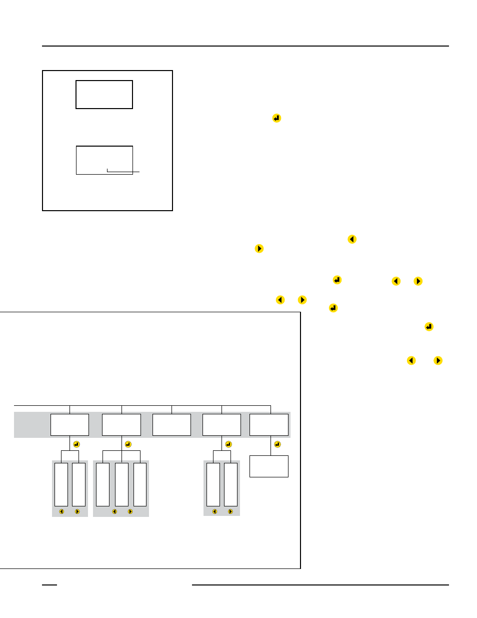
Figure 8. Run mode display
DIST mm
1475
DIST in
32512
Sensor measures 1475 mm distance
to target.
Sensor measures 325.12" distance
to target.
Imaginary
decimal
point
Mode Q1
Teach-In
(Set Q1)
Teach 1.1
Teach 1.2
Hyst 1
Teach-In
(Setup)
Mode Q2
Teach-In
(Set Q2)
Teach 2.1
Teach 2.2
Hyst 2
Mode Analog
Teach-In
Analog
Copy Q>A
Teach A1
Teach A2
Q1
Q2
QuickSet
(Enter)
4564 mm
Q1 |||| q2
Factory
(Preset)
Run Mode
Main Menu
Factory > OK
RS422
(see page 13)
Unit
(MM)
Unit > mm
Unit > inch
Password
(OFF)
Password (OFF)
Password (ON)
Serial
(RS422)
Serial > SSI
Serial > Ext. Bus*
Serial > RS422
Password (Required only
if Password option is ON.
Factory preset is Password
OFF.
• Visible Pilot Laser OFF.
• Measuring Laser ON.
• Press or to
light display backlight
• Visible Pilot Laser ON.
• Measuring Laser ON.
• Display backlight ON.
Use or to scroll
between Main Menu
selections.
Use or to
scroll between
selections.
or
or
or
or
or
Offset
(0)
Offset nnnn
Offset > clear?
or
or
or
or
*Ext. Bus requires specialized sensor; not currently available.
Output 1
Menu
Output 2
Menu
Analog Output
Menu