L-gage® lt7 long-range time-of-flight sensor, Figure 3. teach-mode options for each output – Banner L-GAGE LT7 Series User Manual
Page 3
P/N 120244 Rev. B
3
Banner Engineering Corp. • Minneapolis, MN U.S.A
www.bannerengineering.com • Tel: 763.544.3164
L-GAGE® LT7 Long-Range Time-of-Flight Sensor
Output 1
Near
Sensing
Range
Teach
Point Q2.1
Output 2
Far
Sensing
Range
Teach
Point Q1.1
Output 1
Near
Sensing
Range
Output 2
Far
Sensing
Range
Teach
Point
(Q1.1 and
Q2.1 are
identical)
Figure 4. Each discrete output has its own limit for
background suppression
Figure 5. The two discrete outputs share identical limits
for background suppression, but are
complementary
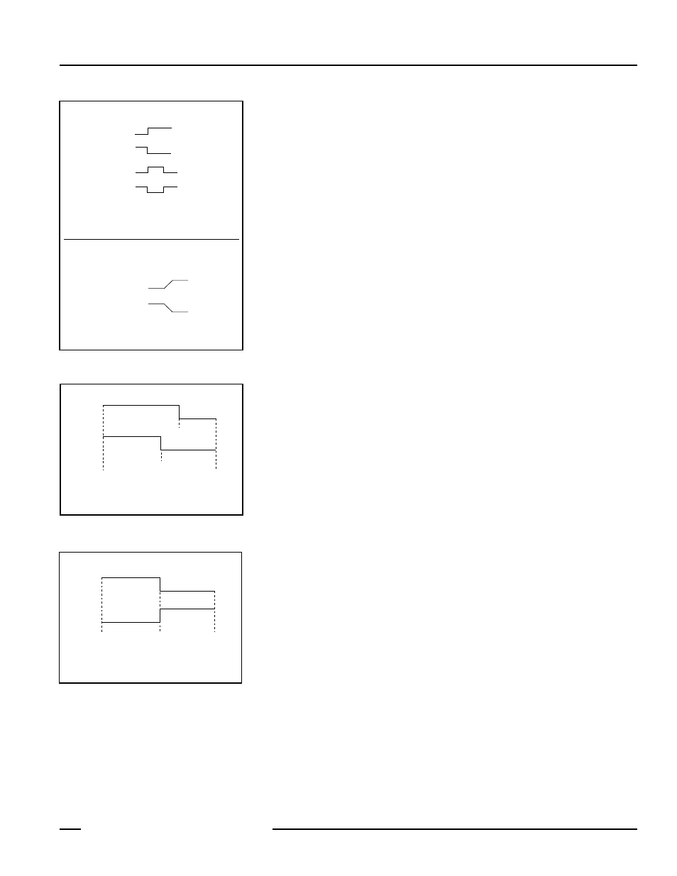
Figure 3. Teach-mode options for each
output
Hysteresis: Manually adjustable in ± 1 mm steps,
symmetrically around the switching point.
(If upper limit is reached, limit value of
measurement range becomes the upper limit.)
Single-point switching
Two-point switching
Two main TEACH methods:
• Individually teach A1 and A2 limits via manual input.
• Copy Discrete Output limits to Analog.
Analog Output (model LT7PIDQ only) –
NOTE: Analog A1 and A2 must be at least 300 mm apart.
Discrete Outputs (Q1 and Q2) –
Normally Closed
Normally Open
Normally Closed
Normally Open
Mode 1 – Positive Slope
Mode 2 – Negative Slope
A1
A1
A2
A2
Password. A Password function is included to provide a measure of security for the
sensor settings. If Password is set to ON, the password must be entered before any
programming can take place. The password is always “1234”; it cannot be changed.
(The security results from the requirement to know the entry procedure and the timeout
function. If the password is not entered within approximately 10 seconds, the sensor will
return automatically to Run mode.) Measuring continues in the “background” while the
password is entered).
Select measurement in millimeters or inches (actually, hundredths of an inch. To “see”
whole inches on the display, imagine a decimal point on the display, two spaces in from
the right; see Figure 8).
Offset. An offset value can be entered or taught, which increases or reduces the measured
value, in order to compensate for a mounting position that does not correspond with the
zero point of the device. (For example, 3000 actual distance minus 1200 mm offset value
equals 1800 mm adjusted output value.) The offset value can be up to 100,000 mm (or
corresponding inch value); the plus or minus is also selectable. The offset value reverts to
0 if the factory preset function is used. The offset value applies equally to all outputs.
Factory Preset. Sensor easily reverts to factory preset conditions:
Teach-In –
Q1 and Q2 (Discrete) – single switchpoint (full sensing range), ± 5mm hysteresis
QA (Analog) – Mode 1, rising (positive slope, full sensing range)
Offset – 0
Unit – mm
Serial – RS422
Password – OFF
Multiple Outputs. The sensing distance can be taught using QuickSet, Teach-In, or by
manually entering the distance value(s). Either one or two sensing conditions may be
taught for each output (see Figures 4 and 5).
Discrete outputs: The two outputs may be configured identically or they may have
completely independent limits and configuration. One or two sensing conditions can be
taught for each. If one condition is taught, the output sets a switching threshold, around
which the selected hysteresis is applied. The two-point TEACH result differs, depending on
whether QuickSet or TEACH-IN is used to set the limits. In QuickSet, the sensor averages
the two taught values, then centers a 200 mm window around the averaged point (100
mm to each side). TEACH-IN window limits remain as taught; the window can be any
size. The selected hysteresis is applied to each threshold and window near limit and far
limit equally, no matter how they are taught.
Analog outputs: Analog limits 1 and 2 must be at least 300 mm apart. Individually teach
4 mA (A1) and 20 mA (A2) points or use the Copy function (selectable in the Analog
Output Mode menu) to copy the discrete limits (only the first limits of discrete 1 and 2) to
the analog output. (If copying Discrete limits to Analog, Discrete limits 1 and 2 must be
at least 300 mm apart, or sensor will not copy those limits.) The order in which they are
copied determines the analog output slope. For Mode 1 (positive slope) selected:
Q1, then Q2 – Limit Q1.1 becomes A1 (4 mA); Q2.1 becomes A2 (20 mA)
Q2, then Q1 – Limit Q1.1 becomes A2 (20 mA); Q2.1 becomes A1 (4 mA)
Manual Adjust: After Teach mode, Manual Adjust (or Edit) may be used to adjust the
value set for any output. It also can be used instead of Teach mode, to input a precise
limit value.