Event counter presets, High word (i/o 3), Low word (i/o 4) – Banner SureCross DX80 Wireless Networks User Manual
Page 8
I/O
Modbus Holding Register
I/O Type
I/O Range
Holding Register Representa-
tion
Terminal Block
Labels
Gateway
Any Node
Min.
Max.
Min. (Dec.)
Max. (Dec.)
16
16
16 + (Node# × 16) Reserved
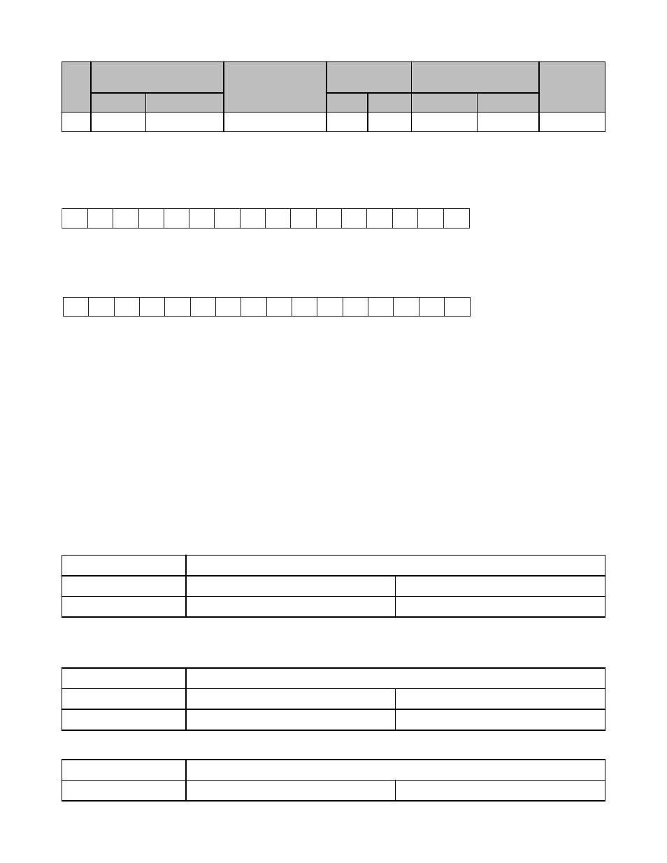
** Two consecutive 16-bit unsigned registers are combined to represent one 32-bit unsigned number for a maximum total count of
4,294,967,295.
High word (I/O 3)
15 14 13 12 11 10 9 8 7 6 5 4 3 2 1 0
+
Low word (I/O 4)
15 14 13 12 11 10 9 8 7 6 5 4 3 2 1 0
Event Counter Presets
The event counter input can be preset from the Node menu system or from a host system using Advanced Control Messages. The LCD
menu system on the Node allows the user to preset event counter values on each available counter input. From the host system, each
device has allocated Node registers 7, 15, and 16 that send preset data to the event counter. When power is applied to the Node, the
counter value is reset to the last saved value. The counter value is saved every hour.
Setting the counter using the preset or clear functions saves the preset value or zeroes in EEPROM.
Host Control Counter Preset
The event counter input is a 32-bit value that can be preset using the parameter control codes 143 (0x8F) and 144 (0x90). Parameter
control code 143 writes the lower half [15:0] of the counter and code 144 writes the upper half [31:16] of the counter.
Select which counter to preset by defining the Counter Select Mask. The first bit position of the mask (bit 0, right justified) selects the first
counter and the second bit position selected the second counter. Set the Node’s register 16 to the high or low data value. Read Node
register 7 for the transfer acknowledgement. Write to Node register 16 before writing to Node register 15.
There are 16 Modbus holding registers for each SureCross™ device. To calculate the registers for other Nodes, use this equation: Reg-
ister number = I/O# + (Node # × 16). For example, the Gateway is always device 0 (or Node 0), so the Gateway’s holding registers are
registers 1 through 16. The registers for Node 1 are 17 through 32 and the registers for Node 2 are 33 through 48.
Node Reg 16
Low or High Value
Node Reg 15
143 or 144 (0x8F or 0x90)
Counter Select Mask
Node Reg 7
Acknowledge Code 143 or 144
Acknowledge Counter Select Mask
Example: To preset Node 2’s counter 2 to the value 20,567,001 (hex 0139 D3D9), follow these steps:
1. Write the upper word to the counter using control code 144 (0x90).
Node Reg 48
0139
Node Reg 47
0x90
2
Node Reg 39
0x90
2
2. Write the lower word to the counter using control code 143 (0x8F).
Node Reg 48
D3D9
Node Reg 47
0x8F
2
SureCross DX80 FlexPower Counter Node
8
www.bannerengineering.com - tel: 763-544-3164
P/N 136348 Rev. G