Storage mode and sleep mode, Led behavior for the nodes – Banner SureCross DX80 Wireless Networks User Manual
Page 7
• To reduce power consumption and extend battery life, slower sample and reporting rates are used. Faster sample and report rates
can be configured, but this will decrease the battery’s life. For details, refer to the included table of DIP switch configurable parame-
ters.
• The FlexPower switched power management system can operate a FlexPower Node and a sensing device for up to five years on a
single lithium D cell.
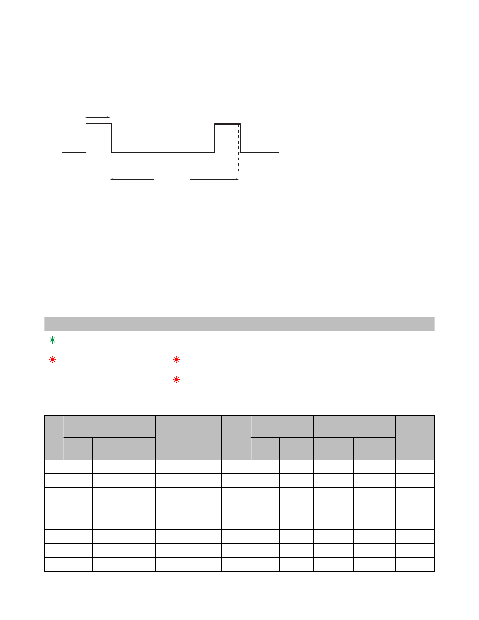
Warmup Time
0 Volts
Switch Power
Sample point
Sample point
Sample interval
Voltage
Storage Mode and Sleep Mode
While in storage mode, the radio does not operate. All SureCross® radios powered from an integrated battery ship from the factory in
storage mode to conserve the battery. To wake the device, press and hold button 1 for five seconds. To put any FlexPower® or integra-
ted battery SureCross radio into storage mode, press and hold button 1 for five seconds. The radio is in storage mode when the LEDs
stop blinking, but in some models, the LCD remains on for an additional minute after the radio enters storage mode. After a device has
entered storage mode, you must wait one minute before waking it.
During normal operation, the SureCross radio devices enter sleep mode after 15 minutes of operation. The radio continues to function,
but the LCD goes blank. To wake the device, press any button.
LED Behavior for the Nodes
After powering up and binding the Gateway and its Nodes, verify all devices are communicating properly. A Node will not sample its
inputs until it is communicating with its Gateway. When testing communication between the Gateway and Node, all radios and antennas
should be at least two meters apart or the communications may fail.
LED 1
LED 2
Node Status
(flashing green)
Radio Link Ok
(flashing red)
(flashing red)
Device Error
(flashing red, 1 per 3 sec)
No Radio Link
Modbus Register Table (Analog or Discrete Configuration)
I/O
Modbus Holding Register
I/O Type
Units
I/O Range
Holding Register Repre-
sentation
Terminal
Block La-
bels
Gate-
way
Any Node
Min.
Max.
Min. (Dec.)
Max. (Dec.)
1
1
1 + (Node# × 16)
Discrete IN 1
-
0
1
0
1
DI1
2
2
2 + (Node# × 16)
Discrete IN 2
-
0
1
0
1
DI2
3
3
3 + (Node# × 16)
Analog IN 1+
mA / V
0.0
20.0 / 10.0
0
65535
A1+
4
4
4 + (Node# × 16)
Analog IN 2+
mA / V
0.0
20.0 / 10.0
0
65535
A2+
...
7
7
7 + (Node# × 16)
Reserved
8
8
8 + (Node# × 16)
Device Message
9
9
9 + (Node# × 16)
Discrete OUT 1
-
0
1
0
1
DO1
SureCross DX80 FlexPower Node
P/N 131296 Rev. L
www.bannerengineering.com - tel: 763-544-3164
7