Wiring diagrams for discrete inputs, Wiring diagrams for discrete outputs, Wiring diagrams for analog inputs – Banner SureCross DX80 Wireless Networks User Manual
Page 6: Switch power (with flexpower)
IP67 Base
IP20 Base
SPx. Switch Power. Provides variable power sources for external
devices. (SP3 and SP4 are not used for the factory default config-
uration of this model.)
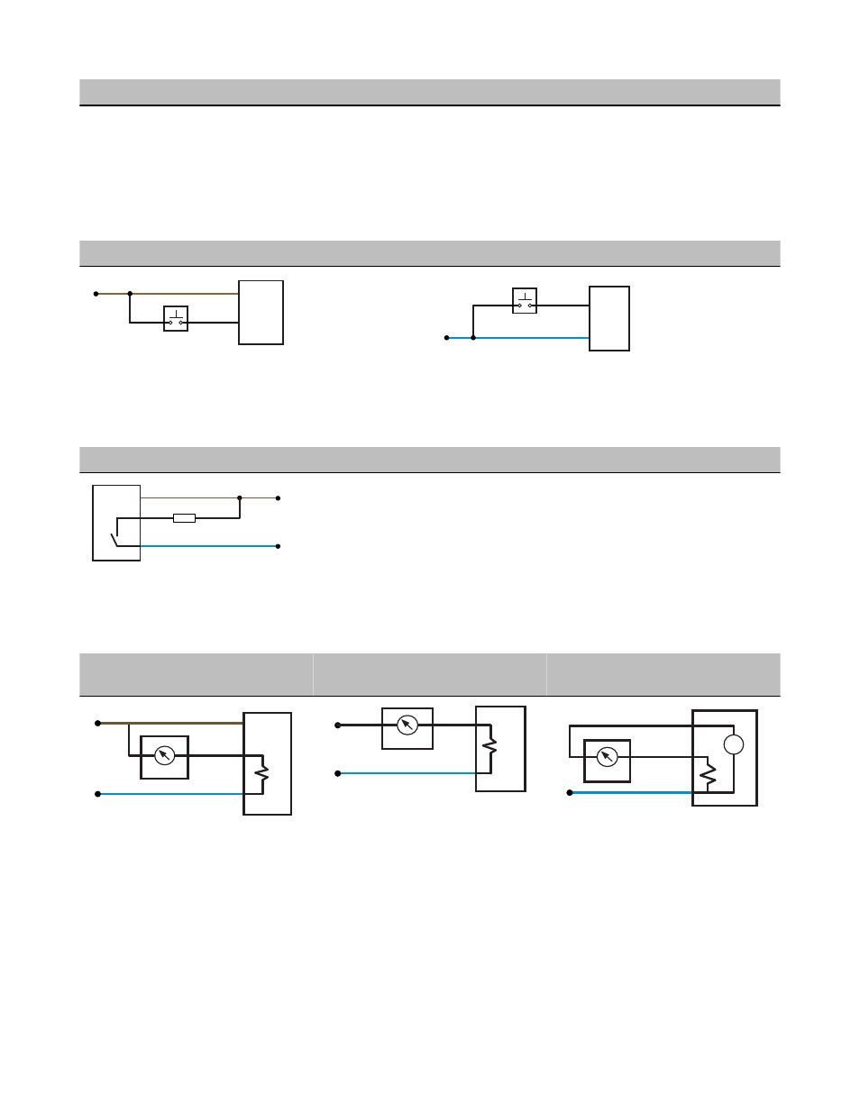
Wiring Diagrams for Discrete Inputs
Connecting dc power to the communication pins will cause permanent damage. For the DX8x...C models, PWR in the wiring diagram
refers to V+ on the wiring board and GND in the wiring diagram refers to V- on the wiring board.
Discrete Input Wiring for PNP Sensors
Discrete Input Wiring for NPN Sensors
DIx
PWR
10-30V dc
DIx
GND
dc common
Wiring Diagrams for Discrete Outputs
Connecting dc power to the communication pins will cause permanent damage. For the DX8x...C models, PWR in the wiring diagram
refers to V+ on the wiring board and GND in the wiring diagram refers to V- on the wiring board.
Discrete Output Wiring (NPN or NMOS)
DOx
GND
PWR
10-30V dc
Load
dc common
Wiring Diagrams for Analog Inputs
Connecting dc power to the communication pins will cause permanent damage. Do not exceed analog input ratings for analog inputs.
Only connect sensor outputs to analog inputs.
Analog Input Wiring (10 to 30V dc Pow-
er)
Analog Input Wiring (4–20mA, 2-Wire,
Externally Powered Sensors)
Analog Input Wiring (4–20mA, 2-Wire,
Switch Powered Sensors)
AIx
PWR
10-30V dc
GND
−
+
sensor
dc common
AIx
GND
dc common
external power
−
+
sensor
+
−
AIx
SPx
GND
−
+
sensor
dc common
(Only possible in models with switch power
(SPx) outputs)
Switch Power (with FlexPower)
Efficient power management technology enables some FlexPower devices to include an internal power supply, called switch power (SP),
that briefly steps up to power sensors requiring 5, 10, or 15V power (ideally, 4 to 20 mA loop-powered sensors). When the switch power
output cycles on, the voltage is boosted to the voltage needed to power the sensor for a specific warmup time. This warmup time denotes
how long the sensor must be powered before a reliable reading can be taken. After the warmup time has passed, the input reads the
sensor, then the switch power shuts off to prolong battery life. The switch power voltage, warm-up time, and sample interval are configu-
rable parameters.
SureCross DX80 FlexPower Node
6
www.bannerengineering.com - tel: 763-544-3164
P/N 131296 Rev. L