Installation / assembly – Bendix Commercial Vehicle Systems EB/ES BRAKES SERVICE MANUAL User Manual
Page 52
51
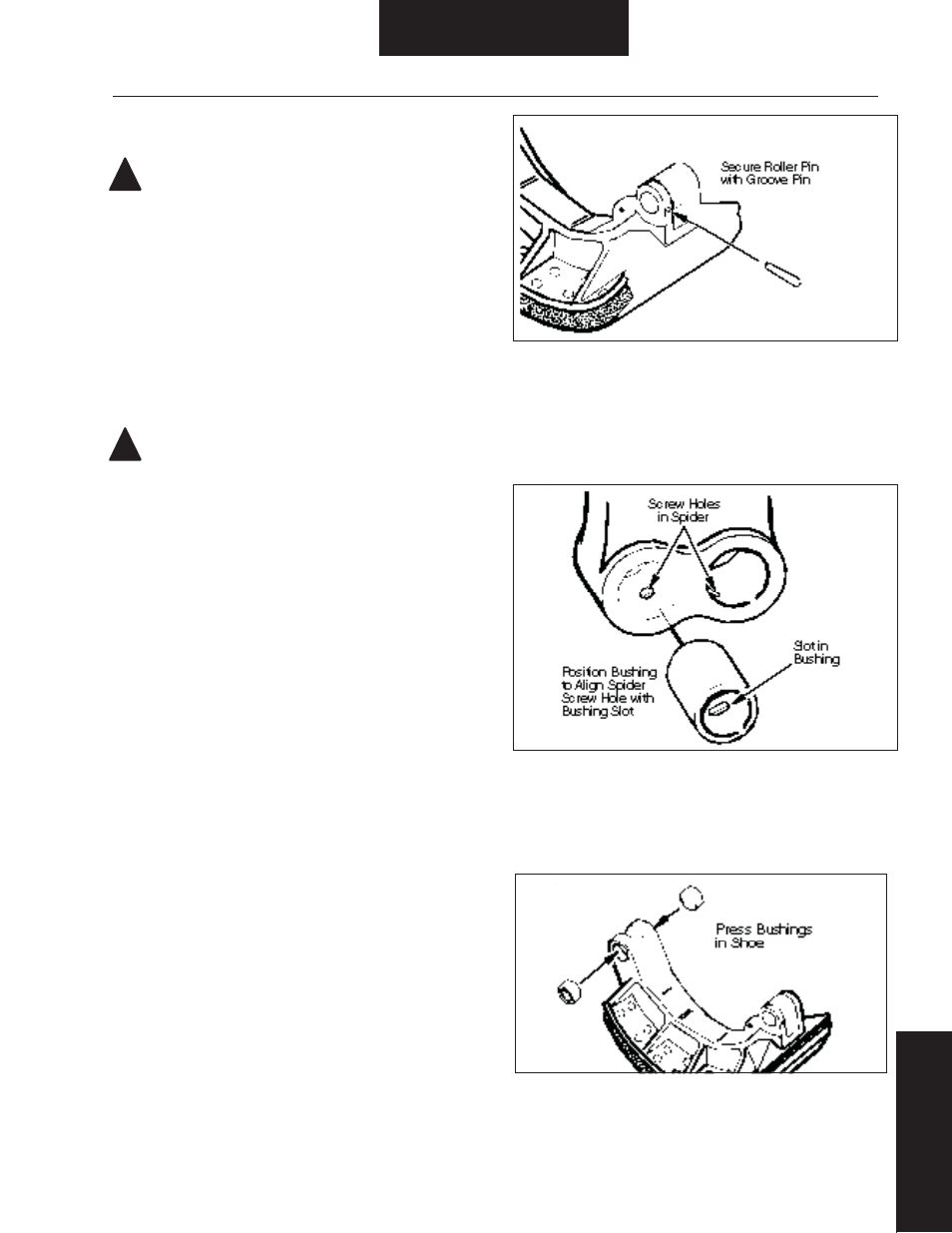
Figure 75. Groove Pin Installation
Figure 76. Spider Anchor Pin Bushing Installation
!
!
Figure 77. Shoe Anchor Pin Bushing Installation
Shoe Installation
Installation / Assembly
ES-165-7-H Severe Duty Brake
WARNING: The long term effects of non-asbestos fi bers,
have not been determined. Therefore, precautions should be
used when handling these materials.
See General Information/lining Material Warning
1. See Inspection & Repair / Replacement to verify that spider,
camshaft, bracket, and brake adjuster are serviceable and properly
installed.
2. During shoe installation, lubricate:
• Roller inside diameter.
• Anchor pin - light fi lm of grease.
CAUTION: Use only grease conforming to NLGI grade #1,
high-temperature, waterproof.
Do Not Lubricate:
• Cam head surface. For effi cient operation, this surface must
remain free of oil, grease or other contaminants.
NOTE: If rollers were removed, replace with new Bendix OEM rollers
and pins.
3. Lubricate roller inside diameter (see Step 2), prior to installa-
tion. Assemble roller and pin to shoe and secure with groove pin.
Stake casting area around groove pin. Refer to Figure 75.
4. After driving out old anchor pin bushings from spider, see
Removal/Disassembly - Shoe Removal, press new anchor pin
bushings in spider, aligning slots in bushing with tapered holes in
spider. Refer to Figure 76.
5. Press anchor pin bushings in brake shoes. Refer to Figure 77.
6. Lubricate anchor pin prior to installation (see Step 2).
7. Place the lower shoe in position on the spider, and install lower
anchor pin, washers and retaining rings. Refer to Figure 78.