Installation / assembly – Bendix Commercial Vehicle Systems EB/ES BRAKES SERVICE MANUAL User Manual
Page 50
49
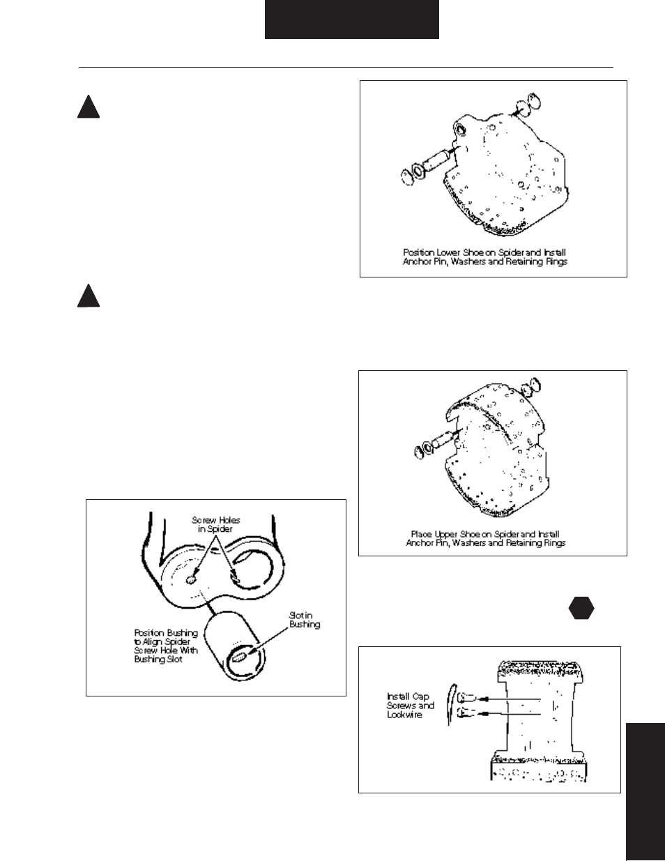
Figure 68. Lower Shoe and Anchor Pin Installation
Figure 70. Cap Screw Installation
Figure 69. Upper Shoe and Anchor Pin Installation
Figure 67. Anchor Pin Bushing Installation
T
!
!
Installation / Assembly
Shoe Installation
WARNING: The long term effects of non-asbestos fi bers,
have not been determined. Therefore, precautions should be
used when handling these materials.
See General Information / Lining Material Warning
ES-165-7M Heavy Duty Brake
1. See Inspection & Repair / Replacement to verify that spider
camshaft, bracket, and brake adjuster are serviceable and properly
installed.
2. During shoe installation, lubricate:
• Shoe roller recess.
• Anchor pin - light fi lm of grease.
CAUTION: Use only grease conforming to NLGI grade #1,
high-temperature, waterproof.
Do Not Lubricate:
• Cam head surface. For effi cient operation, this surface must remain
free of oil, grease or other contaminants.
3. After driving out old anchor pin bushings from spider, see
Removal/Disassembly - Shoe Removal, press new anchor pin
bushings in spider, aligning slot in bushing with tapped holes in
spider. Refer to Figure 67.
4. Lubricate anchor pins during installation (see step 2)
5. Place the lower shoe in mounting position on spider, and
install lower anchor pin, washers and retaining rings. Refer to
Figure 68.
6. Place upper shoe in mounting position on spider, and install upper
anchor pin, washers and retaining rings. Refer to Figure 69.
7. Install cap screws in spider to secure anchor pins. Tighten to
proper torque (see Specifi cations chart), then lock wire.
Refer to Figure 70.