Installation / assembly – Bendix Commercial Vehicle Systems EB/ES BRAKES SERVICE MANUAL User Manual
Page 44
43
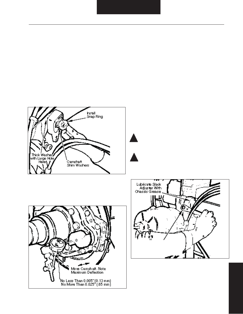
5. Install camshaft shim washers and snap ring. Refer to Figure 54.
Check and adjust camshaft axial play (see step 6).
NOTE: Camshaft axial play must be checked before camshaft
installation is complete. Follow instructions below.
6. Mount a suitable dial indicator with plunger referencing end of
cam head. Refer to Figure 55.
7. Pull inboard on brake adjuster end of cam to take up end play.
8. Zero dial indicator.
9. Push outboard on brake adjuster end of cam and note maximum
reading. If necessary, add or delete camshaft shim washers to obtain
end play between 0.005" - 0.025" (0.13 - .65 mm) with brake
adjuster centered between air chamber bracket and snap ring groove.
10. Pressure lubricate brake adjuster according to manufacturer’s
instructions. Pressure lubricate air chamber bracket until grease
fl ows out of brake adjuster end of tube. Refer to Figure 56.
CAUTION: Grease should not fl ow out end of tube toward cam
head. If it does, seal is defective and must be replaced.
CAUTION: Do not replace existing grease fi tting with a
pressure relief type. Only standard non-vented fi ttings are to
be used with spring loaded lip seals.
Figure 55. Brake Adjuster End Play Check
Figure 56. Brake Adjuster Lubrication and Adjustment
Figure 54. Shim Washer and Snap Ring Installation
!
!
Installation / Assembly
Bracket/Camshaft/W
asher
Installation
SPECIAL NOTE: For ES-1 655,6,7D,L Steer axle brakes using the
horse collar spring retention system, position the cam head
washer with the “stamped spider” arrow pointing towards the
center of the spider. The horse collar should be placed over the
cam tube fi rst, then the ES washer & fi nally the cam.
Cam Head Washer Installation
Brake Adjuster Installation
1. Verify that brake adjuster is serviceable, see Inspection - Brake
Adjuster Inspection.
2. Install brake adjuster inner washer on camshaft. Washer is
identifi ed by its 0.060" thickness and larger hole (see Figure 54).
3. Apply a thin fi lm of chassis grease to brake adjuster splines.
4. Install brake adjuster on camshaft in the same position as noted
before removal.
Rotate Adjuster Nut
Until Brake Adjuster is
Aligned With Clevis Hole