Installation / assembly, Shoe and lining installation – Bendix Commercial Vehicle Systems EB/ES BRAKES SERVICE MANUAL User Manual
Page 46
45
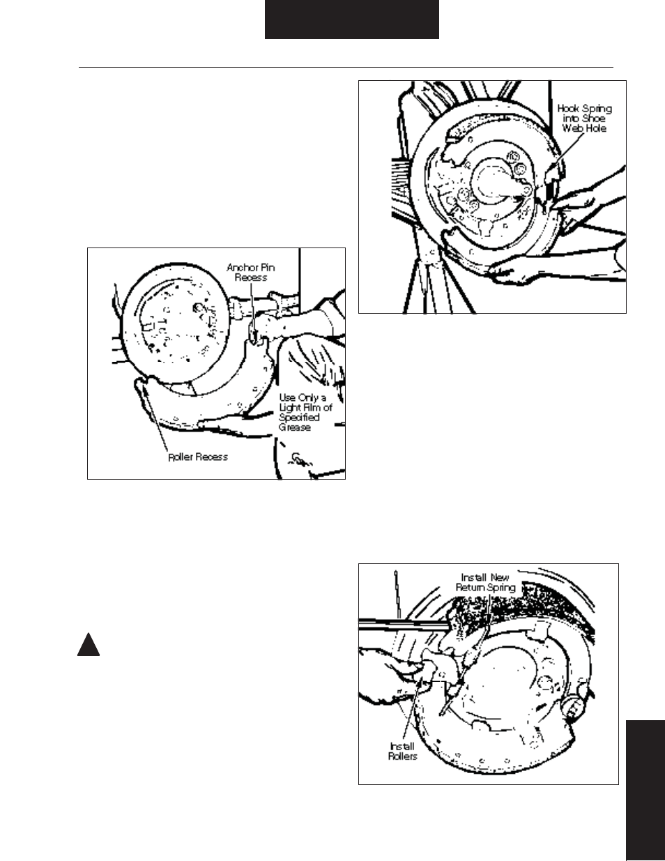
Figure 58. Shoe Retaining Spring Installation
Figure 59. Shoe Return Spring and Roller Installation
!
Installation / Assembly
Brake Adjuster/Shoe
and
Lining Installation
Shoe and Lining Installation
An index to the location of shoe installation procedures is provided
in Table 8. Locate the brake model under service to identify the
location of the appropriate shoe installation procedures.
EB/ES-150-4L Brake
1. Verify that spider, camshaft, air chamber bracket, and brake
adjuster are serviceable and properly installed.
NOTE: See General Information - Parts Nomenclature for shoe
hold-down spring variations.
2. Apply a thin fi lm of grease to cam roller and anchor pin recesses
of each shoe web. Refer to Figure 57.
CAUTION: Use only grease conforming to NLGI grade #1,
high-temperature, waterproof.
3. Position upper shoe and lining web on anchor pin and rotate
down. Continue rotation until shoe is held in place by shoe hold-
down spring.
4. Hook one end of a new shoe retaining spring into hole in upper
shoe web so coil lays across anchor pin. Refer to Figure 58.
5. Hook opposite end of spring into hole on lower shoe web.
6. Stretch spring to allow positioning of lower shoe web against
anchor pin.
7. Rotate lower shoe into position on spider.
8. Hook end of a new shoe return spring in lower shoe web hole.
Using a screwdriver for assistance, stretch shoe return spring to
hook it in upper shoe web hole. Refer to Figure 59.
9. Using a large screwdriver or lever with tip, stretch shoe return
spring to allow insertion of a new cam roller on upper shoe web.
10. Install a new cam roller on lower shoe web in same manner.
Figure 57. Shoe Web Lubrication