Installation / assembly – Bendix Commercial Vehicle Systems EB/ES BRAKES SERVICE MANUAL User Manual
Page 48
47
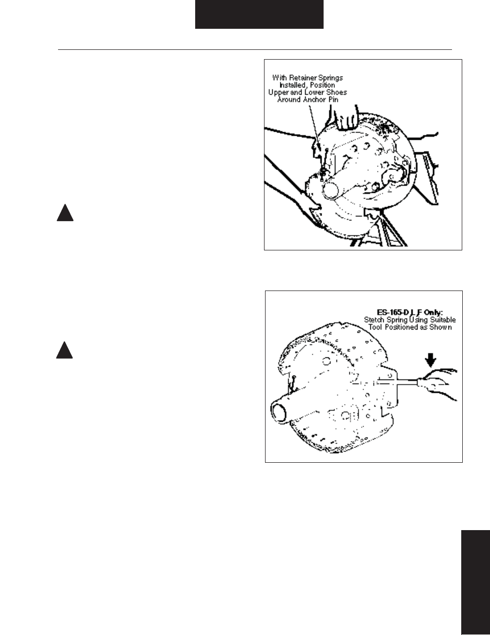
Figure 62. Upper and Lower Shoe Positioning
Figure 63. Shoe Return Spring Installation
!
!
Installation / Assembly
Shoe and Lining
Installation
All EB (except EB-150-4L) and ES-165 5/6/7/8D,F,L
NOTE: The following procedures are divided into sections,
identifi ed by brake model numbers.
1. See Inspection & Repair / Replacement to verify that spider
camshaft, bracket, and brake adjuster are serviceable and properly
installed.
2. During shoe installation, lubricate:
• Shoe roller recess - one-piece roller.
• Roller I.D. - two-piece roller.
CAUTION: Use only grease conforming to NLGI grade #1,
high-temperature, waterproof.
Do Not Lubricate:
• Cam head surface. For effi cient operation, this surface must
remain free of oil, grease or other contaminants.
3. Hook ends of new retainer springs into holes in both shoe
tables, hooks pointing out.
4. Position upper and lower shoes around anchor pin. Refer to
Figure 62.
WARNING: The long term effects of non-asbestos fi bers,
have not been determined. Therefore, precautions should be
used when handling these materials.
See General Information / Lining Material Warning
5. Install a new shoe return spring. Refer to Figure 63.
NOTE: On ES-165-D, 1, F, a lever may be required to assist in
hooking shoe return spring.