Rockwell Automation LDL Ironless Linear Servo Motors User Manual
Page 72
72
Publication LDL-UM001A-EN-P- March 2009
Appendix B Interconnect Diagrams
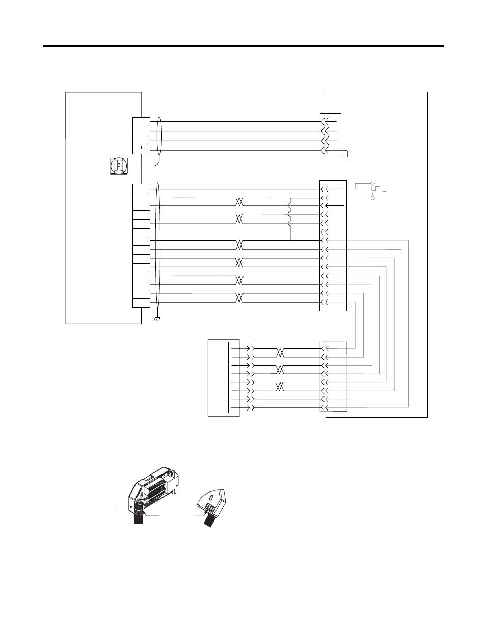
Wiring Example for Ultra Drive and LDL-xxxxxxx-xHT11 Linear Motor with a TTL
Encoder
Cable Shield
Clamp
Note 1
Motor Power Cable
Note 2
Feedback Cable
Note 2
Refer to low profile connector
illustration (lower left) for proper
grounding and shield termination
techniques.
Wire color shown for Renishaw
RGH22 linear incremental encoder
with its reference mark actuator
installed.
TTL Encoder
LDL-Series Linear Motor Coil
Three-phase
Motor Power
Thermal
Switch
A
B
C
SIN+
SIN-
COS+
COS-
IM+
IM-
+5VDC
ECOM
COS+
COS-
IM+
IM-
+5V DC
ECOM
TS-
N/C
N/C
TS+
S3
S2
S1
Green
White/Green
Gray
WHT/Gray
Blue
WHT/Blue
Yellow
WHT/Yellow
WHT/Orange
Red
WHT/Red
SIN+
SIN-
Black
WHT/Black
4
3
2
1
Green/Yellow
Blue
Black
Brown
GND
W
V
U
10
9
6
5
3
4
2
1
1
4
2
5
3
6
8
7
15
13
14
16
17
2090-CPWM4DF-xxAFxx,
2090-XXNPMF-xxSxx
2090-XXNFMF-Sxx or
2900-CFBM4DF-CDAFxx
1
2
3
4
5
10
14
6
11
12
13
8
2090-UXBB-DM15
Ultra3000 Drive
Motor Power
(TB1) Connector
Motor Feedback
(CN2) Connector
Motor Feed Breakout Board
Cable Tie
Ground techniques for
feedback cable shield.
Exposed shield secured
under clamp.
Motor Power Cable
Note 2
Feedback Cable
Note 2
Refer to low profile connector
illustration (lower left) for proper
grounding and shield termination
techniques.
TTL Encoder
LDL-Series Linear Motor Coil
Three-phase
Motor Power
Thermal
Switch