Rockwell Automation 9000 Series Sensor User Manual
Page 24
16
Entek 9000 Series Sensor Installation Guide
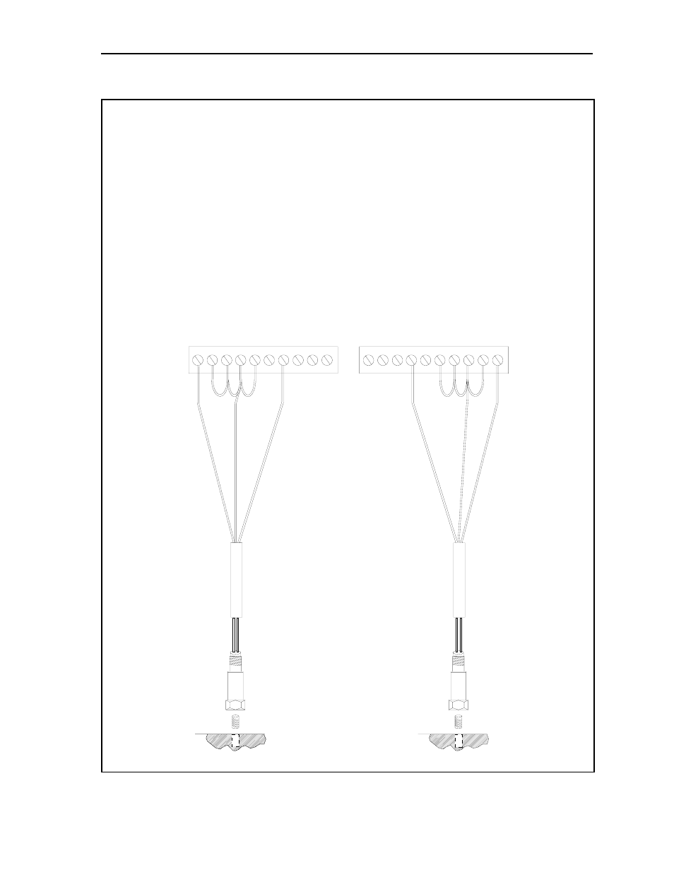
Connecting 9000 Series Sensors to Monitors
Co
mmon
Ch
ann
e
l A
S
ign
al
P
in
A
- S
ignal
Pin
B
- Com
m
o
n
C
abl
e
sh
iel
d
not
co
nn
ecte
d
at
th
is
end
Not
e
: If
shi
e
ld
i
s
co
nne
cte
d
at th
e
tr
an
sduce
r, d
o
n
o
t
gro
u
n
d
th
e
s
h
ie
ld
a
t th
e
5800
mo
nitor
e
n
d
. If
s
h
ie
ld
con
nect
ion
i
s
u
n
k
no
wn
a
t th
e
tw
o
pin
co
n
n
e
c
to
r,
o
h
m o
u
t a
nd ver
ify be
fo
re wir
ing.
1
SIG
A
N
D
+
24 V
D
C
2
3
S
IG GN
D
CO
MMO
N
4
5
6
0-
5 VDC RECOR
D
ER CHAN A
7
GND
8
4-
20
MA C
URREN
T
TRAN
SMITTER C
H
AN
A
9
-2
4
V
D
C
10
A
N
AL
YZ
ER
CHA
N
A
1
A
N
AL
YZE
R
CH
AN B
2
+
24
VDC
3
4-
20
MA C
URREN
T
TRAN
SMITTER C
H
AN
B
4
GND
5
0-
5 VDC RECOR
D
ER CHAN B
6
7
8
S
IG GN
D
CO
MMO
N
9
10 S
IG
AND
+24 VCD
P
in
A
- S
ignal
Pin
B
- Com
m
o
n
Sh
iel
d
Co
mmo
n
Cha
nne
l B
Si
gna
l
S
h
ie
ld
C
abl
e
sh
iel
d
not
co
nn
ecte
d
at
th
is
end
CO
NNEC
TING
9
0
0
0
SERI
E
S
TRA
N
SDU
C
ERS
TO
A
58
00
M
O
NI
TO
R
Thi
s
sh
ows a
d
u
a
l-
c
han
nel
c
a
rd.
Fo
r
sing
le
-c
h
ann
el
c
a
rd,
o
n
ly w
ir
e
in
to
p cha
n
nel
- 20P PowerFlex DC Drive - Frame D Bimetal Thermostat (10 pages)
- 1336S_F_T_E_R F Frame Snubber Resistor Repl. (6 pages)
- 22-COMM PowerFlex 4-Class DSI (Drive Serial Interface) Network Communication Adapter (4 pages)
- 8-545 Plug In Solid State Relay (2 pages)
- 20-HIM-B1 PowerFlex 7-Class HIM Bezel (DPI) (4 pages)
- 100 Contactors with DC Coil (1 page)
- 100 Contactors with DC Coil (2 pages)
- 20P PowerFlex DC Drive - Frame D Switching Power Supply Circuit Board (6 pages)
- 140G-MTFx_MTHx_MTIx_MTKx Trip Unit Installation-140G-M (6 pages)
- 45BRD Analog Laser Sensor (4 pages)
- 20D Multi-Device Interface Option Board for PowerFlex 700S Drives (20 pages)
- 56RF RFID 18 mm Cylindrical Transceiver (2 pages)
- 42KC Miniature Rectangular: 5V DC Version (2 pages)
- 20P PowerFlex DC Drive - Frame A Switching Power Supply Circuit Board (16 pages)
- 21P-MISC-A-TP-2 Transition Tube Kit #C19-6/7 For PowerFlex 755 w/OEM Liquid Cooling Fr 6/7 Drive (2 pages)
- 42BT Background Suppression Sensor (3 pages)
- 42CB High Speed 18mm Cylindrical (4 pages)
- 140EX-JE2_JE3 Molded Case Circuit Breaker (4 pages)
- 140G-K-EAM1A Early Make Aux Contact for Rotary Handle Oper Mech-140G-K (1 page)
- 140G-K-EAM1A Early Make Aux Contact for Rotary Handle Oper Mech-140G-K (3 pages)
- 20-HIM-A6 PowerFlex (Human Interface Module) (74 pages)
- 42CF General Purpose 12mm Cylindrical (4 pages)
- 20D PowerFlex 700S Phase II Drive Frames 1...6 (80 pages)
- 140EX-HE1_HE2 Molded Case Circuit Breaker (6 pages)
- 140EX-HE1_HE2 Molded Case Circuit Breaker (4 pages)
- 20B PowerFlex 700 Custom Firmware - Pump Off (12 pages)
- 20-WIM-N4S DPI Wireless Interface Module (92 pages)
- 140U H-Frame Circuit Breaker Fixed and Adjustable Thermal Trip (7 pages)
- 140U H-Frame Circuit Breaker Fixed and Adjustable Thermal Trip (2 pages)
- 60-2619, 42JS Swivel/Tilt Mounting Bracket (1 page)
- 22A PowerFlex 4/40/400 Flange Mount (4 pages)
- 45MLA Controller Installation Instructions (16 pages)
- 20P PowerFlex DC Drive - Cooling Fan for Frame A Drives Above 73A at 230V 460V AC (6 pages)
- 42JS Series 7000 to 42JS VisiSight Replacement Kit (2 pages)
- 22A PowerFlex 4-Class HIM Bezel (DSI) (4 pages)
- 42CS Stainless Steel Photoelectric Sensors (4 pages)
- 20L-LL PowerFlex 700L Liquid-to-Liquid Heat Exchanger (40 pages)
- 20P PowerFlex DC Drive - Frame B SCR Modules (20 pages)
- 22B PowerFlex 40 Quick Start FRN 5.xx - 6.xx (161 pages)
- 22B PowerFlex 40 Quick Start FRN 5.xx - 6.xx (22 pages)
- 22F PowerFlex 4M Input RFI Filters (2 pages)
- 45LFM Capacitive Label Sensor (4 pages)
- 140G-Rx Installation Instruction-140G-R (2 pages)
- 140G-Rx Installation Instruction-140G-R (29 pages)
- 22C PowerFlex 400 AC Drive Quick Start - FRN 1-4.xx (28 pages)