Rockwell Automation TL-Series Servo Motor User Manual
Page 17
TL-Series Servo Motor Installation Instructions 17
Publication TL-IN001C-EN-P — March 2005
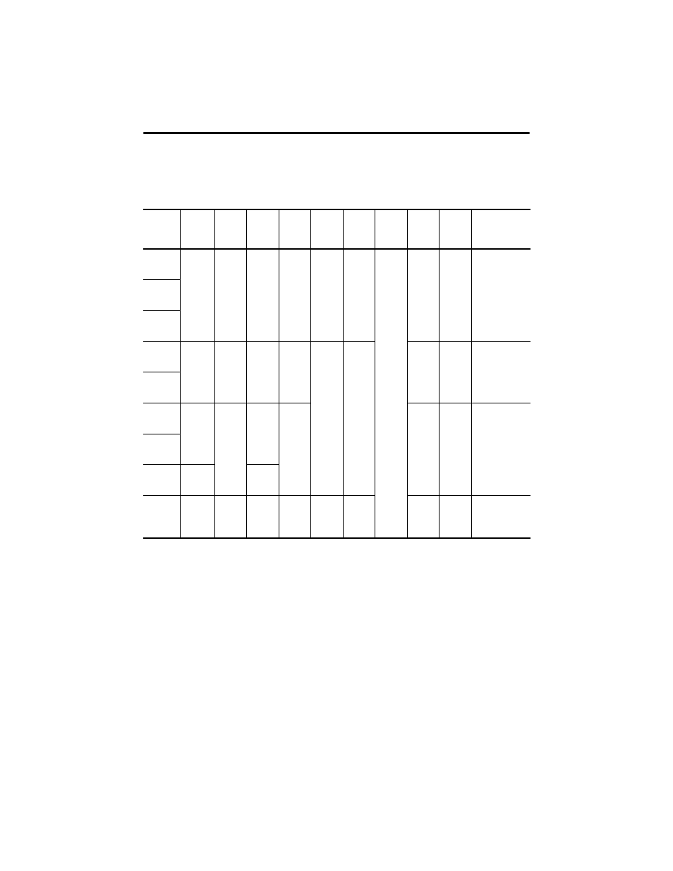
4 Tolerance for this dimension is: TL
-
A1xx -0.021 mm (-0.0008 in.); TL-A2xx -0.025 mm (-0.001 in.); TL-A25xx -0.03 mm (-0.0012 in.);
TL-A310 -0.03 mm (-0.0012 in.); TL-A410 -0.035 mm (-0.0014 in.).
5 TL
-
A1xx has 2 mounting holes, TL-A2xx through TL-A410 have 4 mounting holes.
Mounting holes are S diameter on M diameter bolt circle.
6 Tolerance for cable length is ±50.0 mm (±1.97 in.). Minimum bend radius is 15.00 mm (0.59 in.).
7 Tolerance for this dimension is: -0.20 mm (-0.008 in.).
8 Tolerance for this dimension is: TL-A1xx -0.006 to -0.031 mm (-0.0002 to -0.0012 in.); TL-A2xx and -A25xx -0.012 to -0.042 mm (-0.0005 to
-0.0017 in.); TL-A310 -0.012 to -0.042 mm (-0.0005 to -0.0017 in.); TL-A410 -0.015 to -0.051mm (-0.0006 to -0.0020 in.).
9 Tolerance for x and y dimensions is: TL-A1xx -0.025 mm, TL-A2xx -0.030 mm, TL-A25xx -0.030 mm, TL-A3xx -0.030 mm, and TL-A410
-0.036 mm, length is untoleranced.
Motor
Series
TL-A
N
4
mm
(in.)
NB
mm
(in.)
P
mm
(in.)
S
5
mm
(in.)
T
mm
(in.)
TB
mm
(in.)
CAB
6
mm
(in.)
G
7
mm
(in.)
F
8
mm
(in.)
Key
9
mm
(in.)
110
30.0
(1.1811)
20.0
(0.79)
40.0
(1.57)
4.5
(0.177)
2.5
(0.10)
4.5
(0.18)
300
(11.8)
6.2
(0.244)
3.0
(0.118)
3 x 3 x 15
(0.118 x 0.118 x
0.59)
120
130
220
50.0
(1.9685)
27.0
(1.06)
60.0
(2.36)
5.5
(0.217)
3.0
(0.12)
7.0
(0.28)
9.5
(0.374)
4.0
(0.157)
4 x 4 x 15
(0.158 x 0.158 x
0.59)
230
2530
70.0
(2.7556)
34.0
(1.34)
80.0
(3.15)
6.6
(0.260)
13.0
(0.512)
5.0
(0.197)
5 x 5 x 20
(0.197 x 0.197 x
0.79)
2540
310
80.0
(3.15)
86.0
(3.39)
410
95.0
(3.74)
—
100.0
(3.94)
9.0
(0.354)
7.0
(0.28)
—
18.0
(0.709)
8.0
(0.315)
8 x 7 x 25
(0.315 x 0.276 x
0.985)
NOTE: Metric motor frames are designed to metric dimensions. Inch dimensions are a mathematical conversion.