10 wiring levels and classes – Rockwell Automation SA3100 AC Power Modules User Manual
Page 36
3-18
SA3100 Power Modules
3.10 Wiring Levels and Classes
Drive systems include a wide variety of electrical and electronic circuits. These range
from power circuits that radiate considerable electromagnetic energy to sensitive
electronic circuits susceptible to induced voltages or currents. Solid state digital logic
circuits may be sensitive to transients produced by switching large currents or by
close coupling of field wiring conductors unless properly protected.
System wiring is divided into four basic levels depending upon each circuit’s
susceptibility to noise or its noise-generating capability. The installation wiring for
these levels must be physically separated to prevent poor system performance as a
result of induced noise. Within each level there also may be classes that require
additional grouping and separation of installation wiring. These levels and classes are
defined in ANSI/IEEE Standard 518, Section 6.4.3.1 as follows:
Level 1:
High Susceptibility
Level 2:
Medium Susceptibility
Level 3:
Low Susceptibility
Level 4:
Power
C/W075
1 33.6 (2)
8
54142
1 13.3 (6)
2
54135
1 8.4 (8)
1
54131
C/W100
1 53.5 (1.0)
8
54153
1 13.3 (6)
2
54135
1 13.3 (6)
1
54135
C/W125
1 67.4 (2/0)
8
54158
1 26.7 (3)
2
54147
1 13.3 (6)
1
54135
C/W150
1 107.2 (4/0)
8
54111
1 42.4 (1)
2
54148
1 13.3 (6)
1
54135
C/W200
2 67.4 (2/0)
8
8
54110T
54110B
1 42.4 (1)
2
54148
1 26.7 (3)
1
54142
C/W250
2 85.0 (3/0)
8
8
54111T
54111B
1 67.4 (2/0)
2
54110
1 26.7 (3)
1
54142
C/W300
3 85.0 (3/0)
16 54111
Consult Factory
N/A
N/A
C/W350
3 53.5 (1/0)
24 54109
N/A
N/A
C/W400
3 67.4 (2/0)
24 54110
N/A
N/A
C/W450
3 85.0 (3/0)
24 54111
N/A
N/A
C/W500
3 107.2 (4/0)
24 54112
N/A
N/A
C/W600
3 127.0 (250 MCM) 24 54174
N/A
N/A
W700
-
-
-
-
3 253.0 (500 MCM)
6
54118
1 67.4 (2/0)
1
54110
W800
-
-
-
-
3 253.0 (500 MCM)
6
54118
1 67.4 (2/0)
1
54110
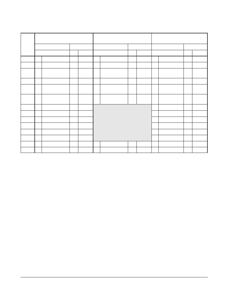
1. Lugs show for DC+ and DC- are based on dynamic brake sizing of 50% of (motor rating x 1.25). select proper lugs based on required
braking torque. Refer to instruction manuals 1336-5.64 or 1336-5.65 for additional information.
2. T & B COLOR-KEYED® Connectors require T & B W117 or TBM-6 Crimper tool or equivalent. Lugs should be crimped according to
manufacturer’s tool instructions. If required, Rockwell Automation can supply lug kits for lugs shown above. Kits do not include crimping
tools. Consult factory for kit information.
3. 5/16 inch stud. All other studs are 3/8 inch.
Table 3.4 – Lug Selection
Power
Module
No.
AC Input R,S,T
Output U,V,W, and PE
DC+ DC-
1
TE
Cable (per phase)
T&B Part No.
2
Cable (per phase)
T&B Part No.
2
Cable (per phase)
T&B Part No.
2
Qty mm
2
(AWG)
Qty Number Qty mm
2
(AWG)
Qty Number Qty mm
2
(AWG)
Qty
Number