Rockwell Automation SA3100 AC Power Modules User Manual
Page 112
F-2
SA3100 Power Modules
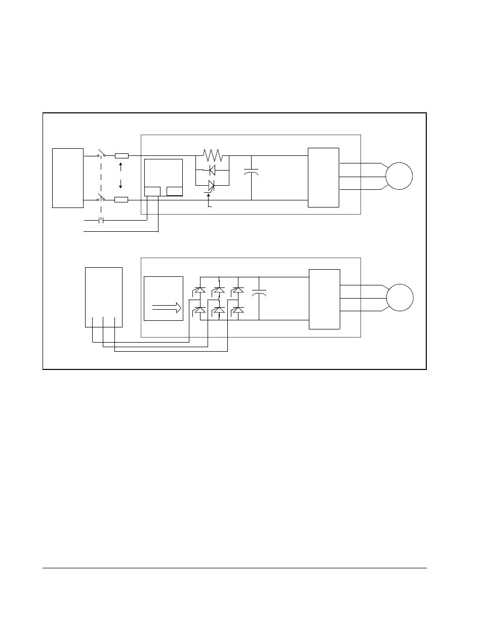
Note that pre-charge circuit power on C frame or larger common bus units must be
interlocked with the bus disconnect as shown in figure F.2 below. The connection is
made to TB1 (pins 1 and 3) on the pre-charge printed circuit board. Either AC or DC
voltage can be used. The selection is determined by the setting of jumper W1. 115
VAC is the default jumper setting.
Input power (either via an external DC bus supply or 3-phase AC input, depending
upon the Power Module) can be turned on either before or at the same time that bus
control is enabled. On low horsepower (B frame) or common bus units (C frame and
larger) the pre-charge semiconductor is initially off, allowing the bus capacitors to
charge as soon as power is applied to the Power Module. This occurs regardless of
whether or not bus control has been enabled by the programmer. In the absence of
explicit control by the programmer, current to the bus is limited by the pre-charge
resistors. On stand-alone (AC input) Power Modules, the bus is charged when bus
control is enabled. This allows a phase advancing front end to charge the bus
capacitors.
The programmer initiates control of the charging process by setting the BUS_ENA@
bit (register 100/100, bit 4). Normally, the PMI processor waits for the rising edge of
this bit to start the process. However, if this bit is on at power-up, the PMI processor
will interpret this as a positive transition.
Figure F.2 – Internal DC Bus Schematics (C Frame or Larger Power Modules)
Pre-charge
Board
DC Bus
Capacitors
Power
Devices
Pre-charge Resistor
AC
Motor
Pre-charge Semiconductor
External
DC Bus
Fuses
C Frame or Larger DC Input SA3100 Power Modules
W1 Setting: 1-2 = 24V DC; 2-3 = 120V AC
+
–
Customer’s Fused
Disconnect
Pre-charge
Board
DC Bus
Capacitors
Power
Devices
AC
Motor
AC
Input
C Frame or Larger AC Input SA3100 Power
1 2 3
1 2 3
TB1
W1
120V AC
or
24V DC
L1 L2 L3