F.1 modifying internal dc bus voltage thresholds – Rockwell Automation SA3100 AC Power Modules User Manual
Page 115
SA3100 Internal DC Bus Control
F-5
F.1
Modifying Internal DC Bus Voltage Thresholds
The programmer can use three different pre-defined tunable variables to specify three
bus voltage thresholds:
•
OVT_E0% overvoltage threshold
•
UVT_E0% undervoltage threshold
•
PLT_E0% power loss threshold
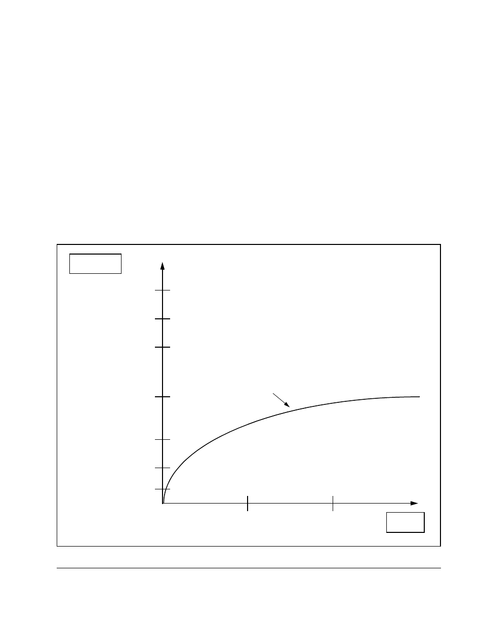
These thresholds define the boundaries for specific operating levels. Figure F.4
shows the relative bus voltage operating ranges and how the tunable variables can
affect these ranges.
Important: The three tunable variables listed above should be tuned before enabling
the execution of the control algorithm in the PMI processor in order to
ensure that internal DC bus voltage warning thresholds are set to levels
appropriate for the application. See instruction manual S-3056, SA3100
Drive Configuration and Programming, for the acceptable value ranges.
Figure F.4 – Internal DC Bus Operating Range
0
1
2
Time in
Seconds
Internal DC
Bus Voltage
Power Loss Threshold
(Tunable PLT_E0%)
Undervoltage Minimum
(Tunable UVT_E0% minus
5% of nominal bus voltage)
Undervoltage Threshold
(Tunable UVT_E0%)
Nominal Bus Voltage
Overvoltage Threshold
(Tunable OVT_E0%)
Overvoltage Maximum
(Tunable OVT_E0% plus
5% of nominal bus voltage)
Hardware Overvoltage
(a preset value)
Normal Charging