Appendix f sa3100 internal dc bus control, Ppendix, Sa3100 internal dc bus control – Rockwell Automation SA3100 AC Power Modules User Manual
Page 111
SA3100 Internal DC Bus Control
F-1
A
PPENDIX
F
SA3100 Internal DC Bus
Control
Both AC and DC input SA3100 Power Modules contain a capacitor bank which must
be charged before the Power Module can produce current. Because the capacitor
bank acts like a DC bus, i.e., it supplies DC power to the inverter section of the Power
Module, the capacitor bank is referred to as an “internal” DC bus.
An external DC bus, which can be used to supply DC voltage to DC input Power
Modules, is provided by the user. This external DC bus is not under the control of the
SA3100 drive.
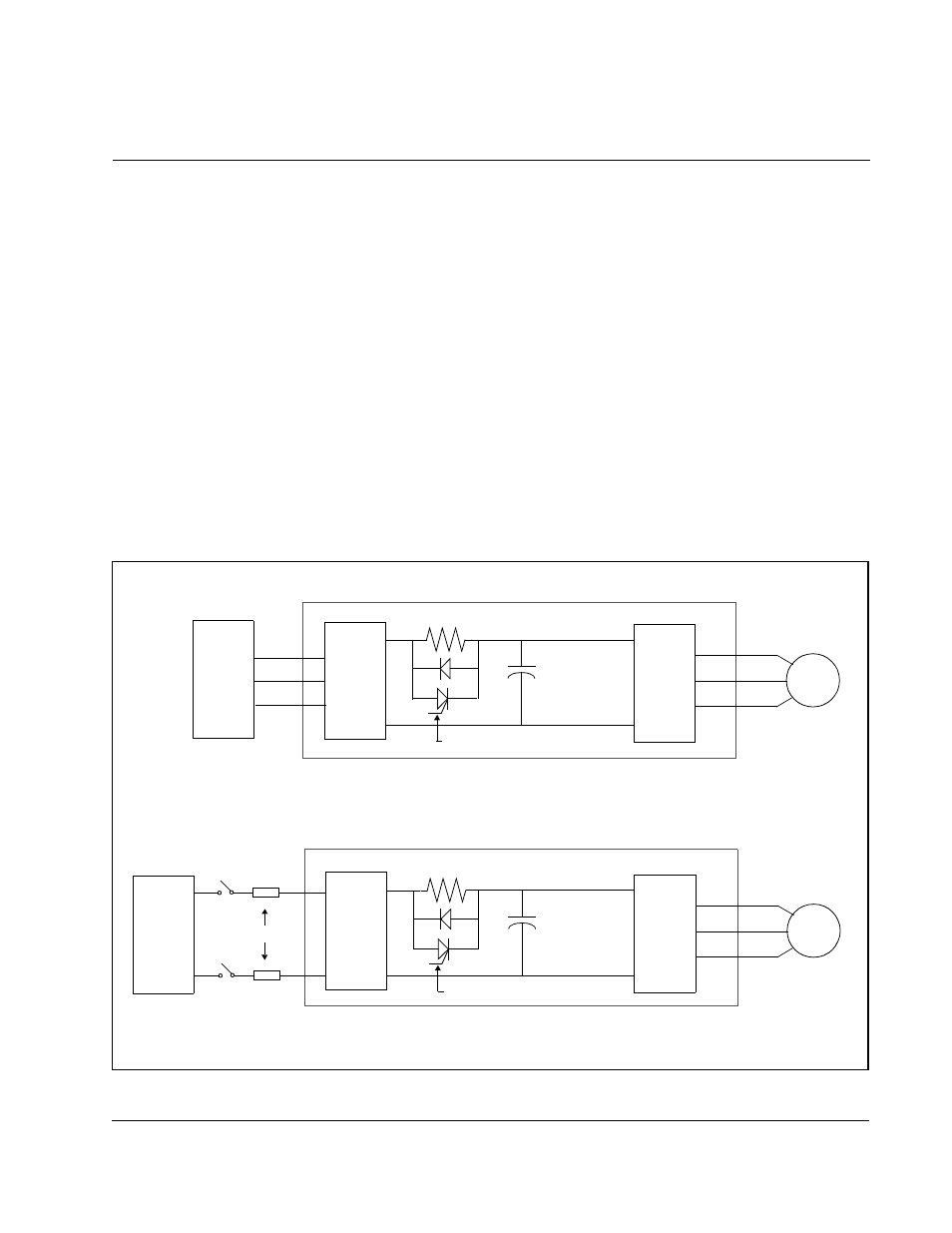
The internal DC bus in each Power Module consists of the capacitor bank, pre-charge
semiconductor, control circuitry, and resistors. See figures F.1 and F.2 for simplified
internal DC bus schematics for both AC and DC input B frame Power Module
configurations.
Figure F.1 – Internal DC Bus Schematics (B Frame Low Horsepower Power Modules)
Bridge
Rectifier
Jumper
Plates
DC Bus
Capacitors
Power
Devices
Pre-charge Resistor
AC
Motor
Pre-charge Semiconductor
External
DC Bus
Fuses
B Frame Low Horsepower DC Input SA3100 Power
Bridge
Rectifier
DC Bus
Capacitors
Power
Devices
Pre-charge Resistor
AC
Motor
Pre-charge Semiconductor
AC
Input
R (L1)
S (L2)
T (L3)
B Frame Low Horsepower AC Input SA3100 Power
+
–
+
–
Customer’s Fused
Disconnect
+
–