Rockwell Automation SA3100 AC Power Modules User Manual
Page 30
3-12
SA3100 Power Modules
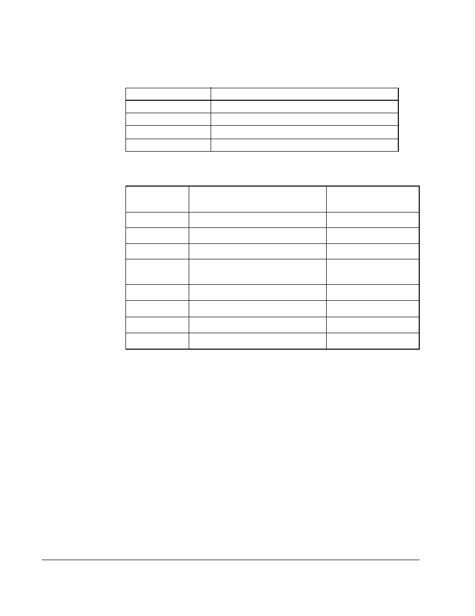
Table 3.2 lists the TB1 signals. Wiring specifications are listed in table 3.3.
1. Use terminals R (L1) and T (L3) for common bus connections in a B-frame unit (see Figure 3.7).
Table 3.2 – TB1 Signals
Terminal
Description
PE
Power Earth Ground
R (L1), S (L2), T (L3)
AC Line Input Terminals
+DC, -DC
DC Bus Terminals
1
U (T1), V (T2), W (T3)
Motor Connection
Table 3.3 – TB1 Wiring Specifications
1
1. Use 75° copper wire only.
Drive
Frame Size
Max/Min Wire Size
2
mm
2
(AWG)
2. Wire sizes given are maximum/minimum sizes that TB1 will accept. These are not recommendations.
Maximum Torque
N-m (lb-in)
B1
8.4/0.8 (8/18)
1.81 (16)
B2
13.3/0.5 (6/20)
1.70 (15)
C
26.7/0.8 ((3/18)
5.65 (50)
D
3
3. These configurations of TB1 are stud type terminations and require the use of lug type connectors to
terminate field installed conductors. Lug kits are available for use with these configurations. Wire size
used is determined by selecting the proper lug kit based on the drive catalog number. Refer to table 3.4.
127.0/2.1 (250 MCM/14)
67.4/2.1 (00/14)
4
4. Applies to 30 kW (40 HP) 200-240V, 45 and 56 kW (60 and 75 HP) 380-480V, 56 kW (75 HP) 500-600V
drives only.
6.00 (52)
6.00 (52)
E
253.0/2.1 (500 MCM/14)
10.00 (87)
303.6/2.1 (600 MCM/14)
23.00 (200)
G
303.6/2.1 (600 MCM/14)
23.00 (200)
H
303.6/2.1 (600 MCM/14)
23.00 (200)