Di me ns io n s – Rockwell Automation MPM-Bxxx Medium Inertia Servo Motor User Manual
Page 14
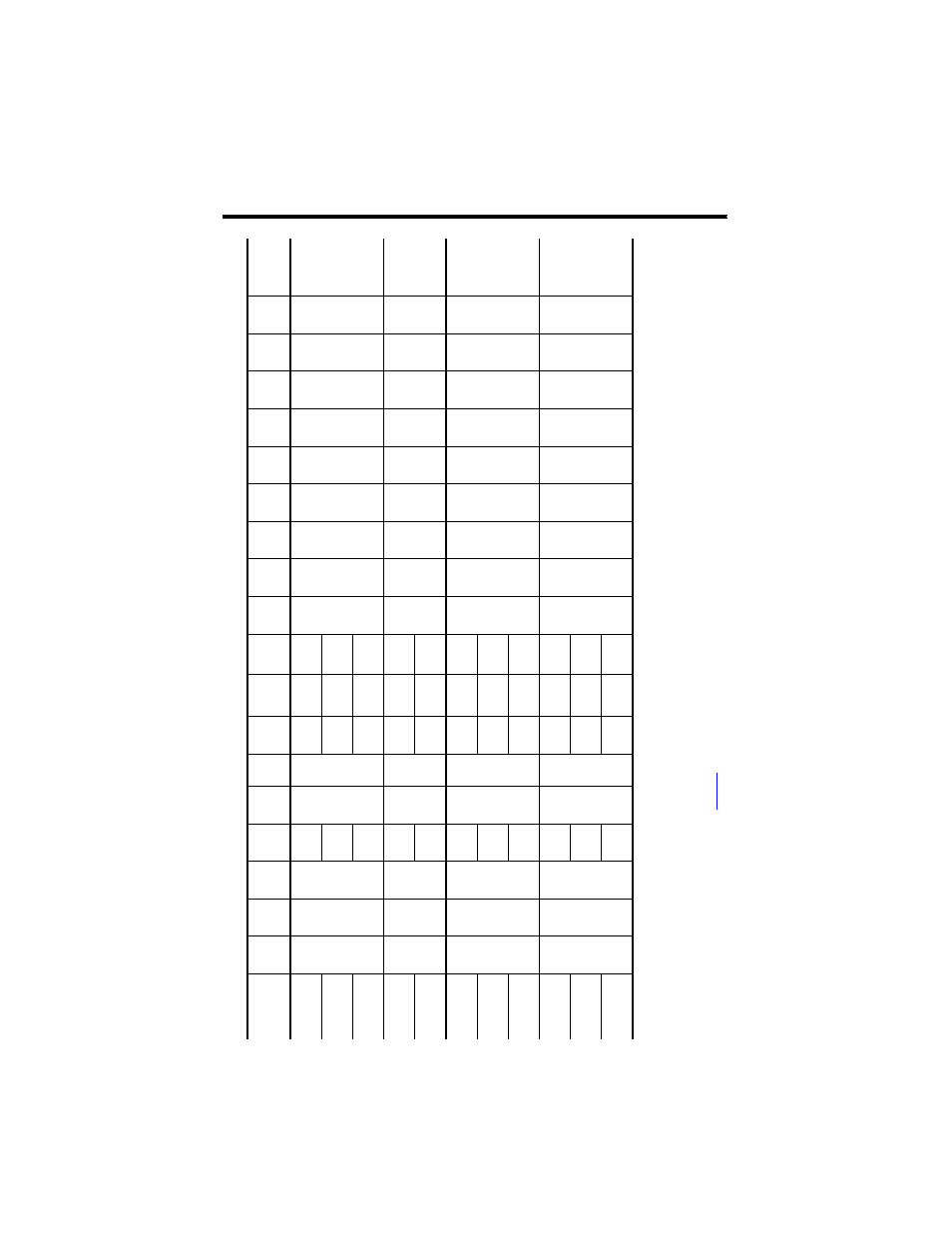
14 MP-Series Medium-inertia Servo Motor with 115 mm to 215 mm Frame Size
Rockwell Automation Publication MPM-IN001D-EN-P - January 2014
Di
me
ns
io
n
s
M
oto
r C
at. No
.
A
D
(1
)
mm
(in.
)
D
mm
(in.
)
HD
(1
)
mm
(in.
)
L
(2
)
mm
(in.
)
L-
LB
(3
)
mm
(in
.)
LA
mm
(in
.)
LB
(2
)
mm
(in.
)
LD
(1
), (2
)
mm
(in.
)
LE
(1
), (2
)
mm
(in.
)
M
mm
(in
.)
N1
mm
(in
.)
N2
mm
(in
.)
P
mm
(in
.)
S
(4
)
mm
(in
.)
T1
mm
(in
.)
T2
mm
(in
.)
F
(5
)
mm
(in
.)
GE
(6
)
mm
(in
.)
En
d o
f S
h
aft
Th
read
an
d
De
pt
h o
f H
ol
e
MPM
-A/
B11
51
90
.9
(3
.5
8)
19
.0
(0
.7
48
)
14
0.1
(5
.5
2)
18
9.9
(7
.4
8)
40
.0
(1
.5
75
)
10.
16
(0
.4
0)
14
9.9
(5
.9
0)
12
4.2
(4
.8
9)
84
.1
(3
.3
1)
115.0
(4
.5
28)
95
.0
(3
.74
)
59
.0
(2
.32
)
98
.3
(3
.87
)
10
.0
(0
.4
01)
2.
74
(0
.1
08)
2.
87
(0
.1
13)
6.
0
(0
.2
36)
3.
5
(0
.1
38)
M6
x
1.0
-6
H
x1
6(
0.
63
)
MPM
-A/
B11
52
21
5.3
(8
.4
8)
17
5.3
(6
.9
0)
14
9.6
(5
.8
9)
10
9.5
(4
.3
1)
MPM
-A/
B11
53
24
0.7
(9
.4
8)
20
0.7
(7
.9
0)
17
5.0
(6
.8
9)
13
4.9
(5
.3
1)
MPM
-A/
B13
02
98
.6
(3
.8
8)
24
.0
(0
.9
45
)
15
5.4
(6
.1
2)
22
8.6
(9
.0
)
50
.0
(1
.9
69
)
12.
19
(0
.4
8)
17
8.6
(7
.0
3)
15
2.9
(6
.0
2)
11
2.8
(4
.4
4)
130.0
(5
.1
18)
110.0
(4
.33
)
70
.3
(2
.77
)
113.7
(4
.48
)
10
.0
(0
.4
01)
2.
74
(0
.1
08)
3.
38
(0
.1
33)
8.
0
(0
.3
15)
4.
0
(0
.1
58)
M8
x
1.2
5
-6
H
x1
9(
0.
75
)
MPM
-A/
B13
04
27
9.4
(1
1.
0)
22
9.4
(9
.0
3)
20
3.7
(8
.0
2)
16
3.6
(6
.4
4)
MPM
-A/
B16
51
11
3.4
(4
.4
7)
28
.0
(1
.1
02
)
18
5.2
(7
.2
9)
28
6.6
(1
1.
28
)
60
.0
(2
.3
62
)
14.
0
(0
.5
5)
22
6.6
(8
.9
2)
20
0.2
(7
.8
8)
16
0.0
(6
.3
0)
165.0
(6
.4
96)
130.0
(5
.12
)
81
.0
(3
.19
)
143.5
(5
.65
)
12
.0
(0
.4
81)
3.
12
(0
.1
23)
3.
38
(0
.1
33)
8.
0
(0
.3
15)
4.
0
(0
.1
58)
M
10x1
.5-
6H
x2
2(
0.
87
)
MPM
-A/
B16
52
33
7.4
(1
3.
28
)
27
7.4
(1
0.
92
)
25
1.0
(9
.8
8)
21
0.8
(8
.3
0)
MPM
-A/
B16
53
38
8.2
(1
5.
28
)
32
8.2
(1
2.
92
)
30
1.8
(1
1.
88
)
26
1.6
(1
0.
30
)
MPM
-A/
B21
52
15
4.0
(6
.0
6)
38
.0
(1
.4
96
)
24
6.5
(9
.7
0)
35
4.6
(1
3.
96
)
80
.0
(3
.1
49
)
17.
8
(0
.7
0)
27
4.6
(1
0.
81
)
23
4.4
(9
.2
3)
16
3.3
(6
.4
3)
215.0
(8
.4
65)
180.0
(7
.09
)
108.0
(4
.25
)
184.9
(7
.28
)
14
.5
0
(0
.5
71)
3.
73
(0
.1
47)
3.
86
(0
.1
52)
10
.0
(0
.3
94)
5.
0
(0
.1
97)
M1
2
x
1.
75
-6
H x
28
(1.1
0)
MPM
-A/
B21
53
40
5.4
(1
5.
96
)
32
5.4
(1
2.
81
)
28
5.2
(1
1.
23
)
21
4.1
(8
.4
3)
MPM
-A/
B21
54
45
6.2
(1
7.
96
)
37
6.2
(1
4.
81
)
33
6.0
(1
3.
23
)
26
4.9
(1
0.
43
)
(1)
See t
he
diagr
am for dimensio
n changes
to
M
PM-
x16
5x
mo
to
rs wit
h a
n M40
pow
er c
onnec
tor
.
(2)
For mo
to
rs
wit
h a brak
e (MPM-
xxxx
xx
-xx
x4
xx
), ad
just dimensions with t
hese
v
alues
:
MPM
-x
11
5 mot
or
s add 48
.5 mm (1.9
1 in.) t
o L, LB
, L
D, and LE
.
MPM
-x
13
0 mot
or
s add 48
.5 mm (1.9
1 in.) t
o L, LB
, L
D, and LE
.
MPM
-x
16
5 mot
or
s add 51
.5 mm (2.0
3 in.) t
o L, LB
, L
D, and LE
.
MPM
-x
21
5 mot
or
s add 88
.9
mm (3.5
0
in.) t
o L, LB
, L
D. and LE
.
(3
)
Toler
an
ce
is ±0.7
(±
0.0
28
).
(4
)
To
le
ran
ce
is
+
0.3
6 (
±
0.
00
7)
fo
r MPM-
x115
an
d M
PM
-x
13
0
mo
to
rs
, a
nd +0.4
3 (±
0.00
8) for MPM
-x
16
5 a
nd MPM-
x21
5.
(5
)
To
le
ran
ce
is
-0
.03 (
-0.0
01)
.
(6
)
Toler
an
ce
is -0
.1 (-
0.00
4) for MPM
-x
11
5x
, -
0.2 (
-0.00
7)
fo
r M
PM-
x13
0x
an
d M
PM-
x16
5x
, an
d
-0
.2 (
-0.00
8)
fo
r M
PM-
x21
5x
.
Re
fe
r t
o K
ine
tix
Ro
ta
ry
Mo
tio
n Sp
ec
ifi
ca
tion
s T
echnica
l Da
ta
, p
ub
lica
tio
n
, f
or
pi
lo
t a
nd
sh
af
t t
ole
ran
ces
.