Communications wiring, Rs232 communications standard, Trusted – Rockwell Automation T8xxx Trusted Communications Interface User Manual
Page 49: Communication interface t8151b
Trusted
TM
Communication Interface T8151B
Issue 21 Apr 10
PD-T8151B
49
6. Communications Wiring
6.1. RS232 Communications Standard
There are two main classes of serial communication defined in the RS232 standard.
DTE (Data Terminal Equipment), such as terminals and computers
DCE (Data Communications Equipment), such as modems.
If standard D-type connectors are used, the convention is to mount Female connectors on the DCE
devices and Male connectors on the DTE devices. Cables between DCE and DTE devices can be
connected 1:1. Cables between devices of the same class require cross-over or ‘Null modem’ cables.
Note that the signal names are from the viewpoint of the DTE. E.g. Transmit Data is sent by the DTE,
but received by DCE.
The Communications Interface is configured as a DTE class device.
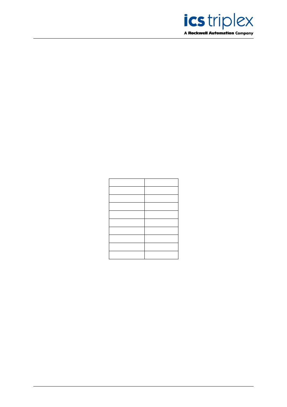
Table 18 below shows the signal directions for the common RS232 circuits.
Circuit Name
Direction
TXD
DTE
DCE
RXD
DTE
DCE
RTS
DTE
DCE
CTS
DTE
DCE
GND
DSR
DTE
DCE
DCD
DTE
DCE
DTR
DTE
DCE
RI
DTE
DCE
Table 18 Signal Directions for RS232 circuits
Table 19 below shows some alternatives for the wiring of Port 1 when using a cable. Note that a male
connector is specified on the cable for connection to the female connector of a DCE device and a
female connector is specified for connection to the male connector of a DTE device. Note that the
labels in the FROM section are shown the same as those on Product Descriptions PD-8151B and PD-
8153. Please refer to these product descriptions for further information on cable wiring.
Cable TC–305–01 (or –02) connects to the Communications Interface module field socket PL5 and
extends the ports below to flying leads. Please refer to Product Description PD-TC300 for further
details.