Rockwell Automation T3411 ICS Regent Monitored Digital Input Modules User Manual
Page 22
Monitored Digital Input Modules (T3411)
2 2
Industrial Control Services
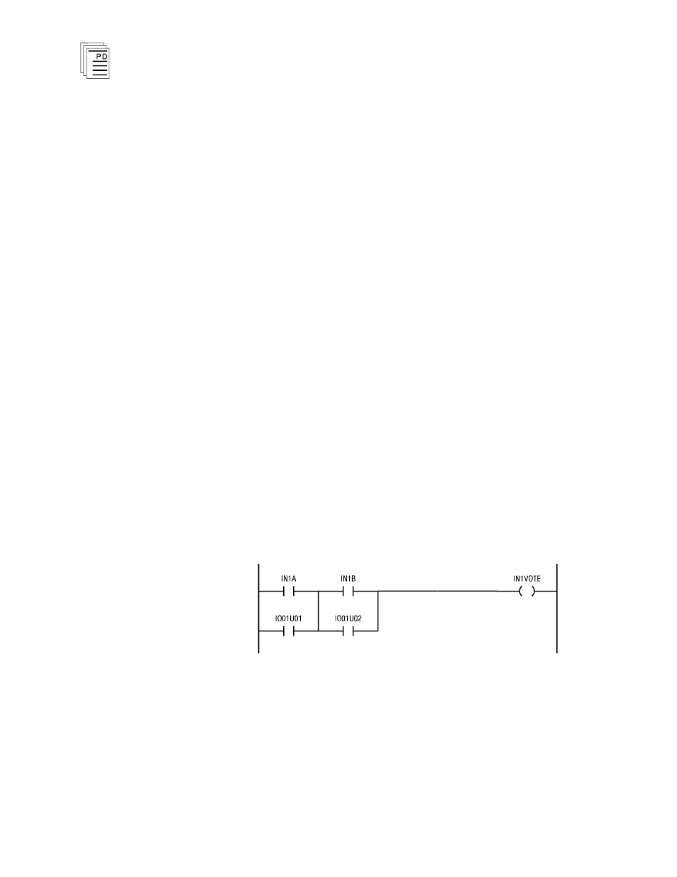
In this example, IN1A and IN1B represent the input
variables from two redundant monitored input modules.
IO01U01 and IO01U02 are the system control relays that
report a fault for the monitored input modules (one installed
in slot 1 of chassis 1 and the other in slot 1 of chassis 2). The
variable IN1VOTE is a shared control relay that will
represent the voted value of the two inputs. This variable
would be used elsewhere in the application program to
represent the status of the field input in the associated safety
interlock logic.
When both input modules are healthy, both inputs must turn
off to turn off the voted result and initiate a trip. Because the
inputs are normally energized, the voted result is normally
on. If a fault occurs on one of the input modules, the voted
result will remain on, eliminating a nuisance trip. Automatic
testing of the input module will detect the fault and the
associated fault bit will be turned on, leaving the voted result
under the control of the remaining healthy input module.
The faulted module can be removed and replaced. After
replacing the input module and performing a voted reset, the
fault bit is turned off, restoring the input configuration to the
dual mode.
Normally De-Energized Inputs
Figure 15 shows a ladder logic rung that would be suited for
normally de-energized inputs that energize to trip.
Figure 15. Dual Voting for Normally De-Energized Inputs.
In this example the variables represent the same status
information as described above for normally energized inputs.
When both input modules are healthy, both inputs must turn
on to turn on the voted result and initiate a trip. Because the
inputs are normally de-energized, the voted result is normally
off. If a fault occurs on one of the input modules, the voted