Rockwell Automation T3411 ICS Regent Monitored Digital Input Modules User Manual
Page 18
Monitored Digital Input Modules (T3411)
1 8
Industrial Control Services
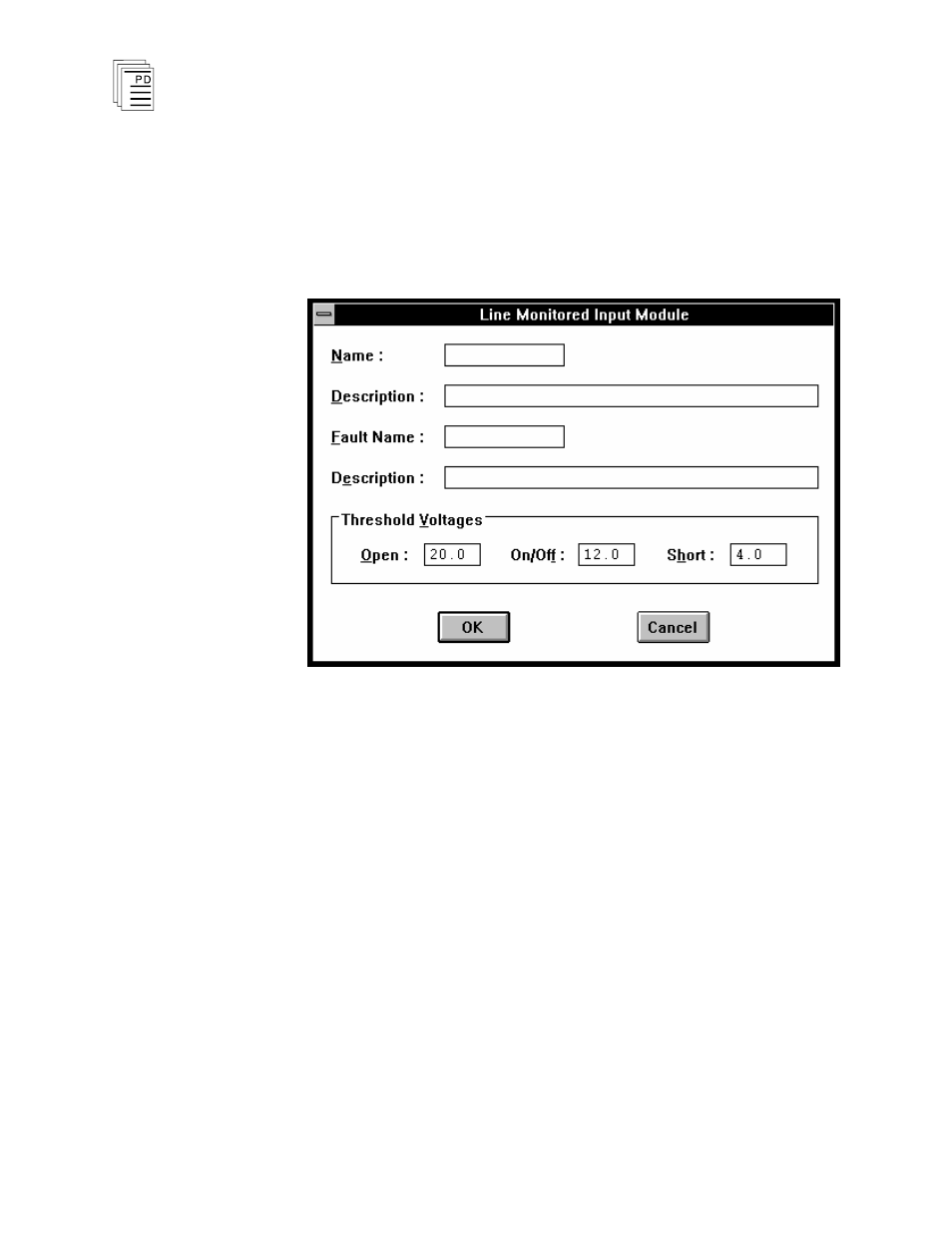
3) Define the Input Module Fields and Thresholds:
With the cursor at the top of the list in the Module
Definition dialog shown in Figure 11, open the Line
Monitored Input Module dialog by pressing Enter or
double clicking on the “(Module)” selection. The dialog box
shown in Figure 12 will open.
Figure 12. Defining the Input Module Fields and Thresholds.
In the module definition dialog you can define a tag names
representing all sixteen input points as a 16-bit word. The
Name field represents the On/Off status of all sixteen
inputs and the Fault Name represents the Line Fault
status of all sixteen inputs.
The module tag names represents the 16 inputs as a
signed, 16-bit integer. In this format, input point one is
the least significant bit (LSB) and input point 16 is the
most significant bit (MSB). Enter tag names up to 12
characters long and descriptions up to 40 characters long.
In the module definition dialog you can also set the
threshold values used to determine the Open Circuit,
On/Off, and Short Circuit input status. Normally these
should be left at the default values of 20, 12 and 4 Vdc
shown in Figure 12. These values are applicable to field
inputs with no line monitor device installed and also for