Rockwell Automation 1794-IP4 Series B FLEX I/O PULSE COUNTER User Manual User Manual
Page 60
6–7
Input, Output and Configuration Files for Analog Modules when used with ControlNet
Publication 1794ĆUM016B-EN-P - August 2002
Definition
Bit
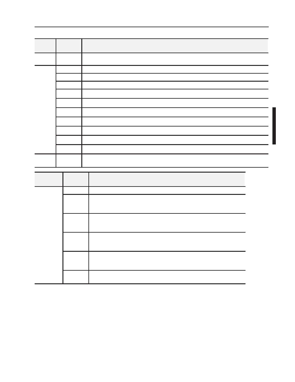
Input
Word
7
Bits 00-15
(00-17)
Counter 31 - pulse counter or high word of 32Ćbit period measurement for channel 3
Read
Word 8
Readback of Control Word 2
Word 8
Bit 00
Positive edge - Channel 0 - measurement ready
Bit 01
Positive edge - Channel 1 - measurement ready
Bit 02
Positive edge - Channel 2 - measurement ready
Bit 03
Positive edge - Channel 3 - measurement ready
Bit 04
Reset Done, Channel 0 - a positive edge on this bit indicates counter 01 reset done
Bit 05
Reset Done, Channel 1 - a positive edge on this bit indicates counter 11 reset done
Bit 06
Reset Done, Channel 2 - a positive edge on this bit indicates counter 21 reset done
Bit 07
Reset Done, Channel 3 - a positive edge on this bit indicates counter 31 reset done
Bit 08-15
Reserved for factory use
Word 9
Bits 00-15
(00-17)
Softwarerevision - version codeof softwareinstalled
Configuration
Word
Bit
Definition
Configuration
Word 0
Control Word 0 - Control word for setting the function of counter 0.
Word 0
Bits 00
Pulse counting and period time measurement selection for Channel 0 -
0 = pulse counting and period time measurement selected
1 = period time measurement selected
Bits 01
Pulse counting and period time measurement selection for Channel 1 -
0 = pulse counting and period time measurement selected
1 = period time measurement selected
Bits 02
Pulse counting and period time measurement selection for Channel 2 -
0 = pulse counting and period time measurement selected
1 = period time measurement selected
Bits 03
Pulse counting and period time measurement selection for Channel 3 -
0 = pulse counting and period time measurement selected
1 = period time measurement selected
Bits 04-15
(04-17)
Reserved