Rockwell Automation 1794-IP4 Series B FLEX I/O PULSE COUNTER User Manual User Manual
Page 44
4–5
Writing Configuration to and Reading Status from Your Module with a Remote I/O Adapter
Publication 1794ĆUM016B-EN-P - August 2002
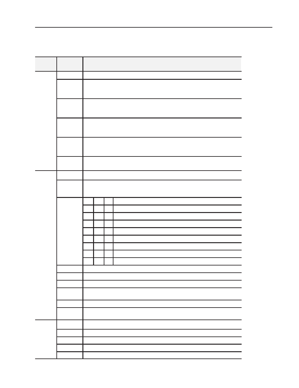
Bit/Word Definitions for the Block Transfer Write Words for the Pulse
Counter Module
Write
Word
Bit
Definition
Write
Word 0
Control Word 0 - Control word for setting the function of counter 0.
Word 0
Bits 00
Pulse counting and period time measurement selection for Channel 0 -
0 = pulse counting and period time measurement selected
1 = period time measurement selected
Bits 01
Pulse counting and period time measurement selection for Channel 1 -
0 = pulse counting and period time measurement selected
1 = period time measurement selected
Bits 02
Pulse counting and period time measurement selection for Channel 2 -
0 = pulse counting and period time measurement selected
1 = period time measurement selected
Bits 03
Pulse counting and period time measurement selection for Channel 3 -
0 = pulse counting and period time measurement selected
1 = period time measurement selected
Bits 04-15
(04-17)
Reserved
Write
Word 1
Control Word 1 - Control word for setting period measurement
Word 1
Bit 00
Clock frequency for period time measurement - Channel 0 -
0 = period time measurement with 10MHz internal clock selected
1 = period time measurement with 1MHz internal clock selected
Bits 01-03
03
02 01
Number of periods for measurement - Channel 0
0
0
0
1 period
0
0
1
2 periods
0
1
0
4 periods
0
1
1
8 periods
1
0
0
16 periods
1
0
1
32 periods
1
1
0
64 periods
1
1
1
128 periods
Bit 04
Clock frequency for period time measurement - Channel 1 - refer to bit 00.
Bits 05-07
Selection of Number of periods for measurement - Channel 1 - see bits 01-03 above
Bit 08 (10)
Clock frequency for period time measurement - Channel 2 - refer to bit 00.
Bits 09-11
(11-13)
Selection of Number of periods for measurement - Channel 2 - see bits 01-03 above
Bit 12 (14)
Clock frequency for period time measurement - Channel 1 - refer to bit 00.
Bits 13-15
(15-17)
Selection of Number of periods for measurement - Channel 1 - see bits 01-03 above
Write
Word 2
Control Word 2 - starts new measurement
Word 2
Bit 00
Start new measurement bit - Channel 0 - when set, start new measurement on positive edge
Bit 01
Start new measurement bit - Channel 1 - when set, start new measurement on positive edge
Bit 02
Start new measurement bit - Channel 2 - when set, start new measurement on positive edge
Bit 03
Start new measurement bit - Channel 3 - when set, start new measurement on positive edge