Rockwell Automation 1794-IP4 Series B FLEX I/O PULSE COUNTER User Manual User Manual
Page 35
3–4
Programming Your Pulse Counter Module
Publication 1794ĆUM016B-EN-P - August 2002
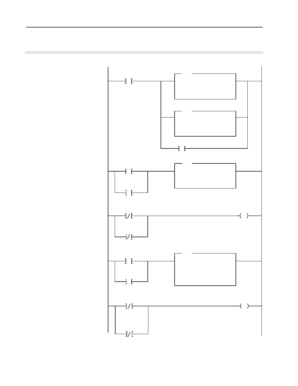
Figure 3.1
SLC Programming for the 1794ĆIP4 Pulse Counter Module
PowerUp Bit
0000
Program Action
S2:1
15
BTR_CONTROL
COP
COPY FILE
SOURCE
DEST
#B3:100
#M0:1.100
LENGTH
3
BTW_CONTROL
COP
COPY FILE
SOURCE
DEST
#B3:110
#M0:1.200
LENGTH
3
COP
COPY FILE
SOURCE
DEST
#M1:1.100
#B3:0
LENGTH
4
0001
BTR PENDING
B3:5
0
This rung configures the block transfer operation
type, length, and RIO address at powerĆup. Bit
B3:100/7 must be set to 1 to indicate a BTRand
bit B3:110/7 must be 0 to indicate a BTW.
U
BTR DONE BIT
B3:0
13
CHECK BTR STATUS
B3:5
1
BTR ERROR BIT
B3:0
12
0002
B3:5
1
COP
COPY FILE
SOURCE
DEST
#M1:1.200
#B3:10
LENGTH
4
0003
BTW PENDING
B3:15
0
CHECK BTW STATUS
B3:15
1
BTRstatus is copied to the B3:0 area when a BTR
is in progress.
Unlatch the bit that continues to check the BTRstatus.
BTW status is copied to the B3:100 area when a
BTW is in progress.
To next page.
0004
U
BTW DONE BIT
B3:10
13
BTW ERROR BIT
B3:10
12
B3:15
1
Unlatch the bit that continues to check the BTW status.
CHECK BTW STATUS
CHECK BTR STATUS
The 1794ĆIP4 module is located in remote I/O rack 1, group 0, slot 0. The 1747ĆSN scanner module is located in slot 1 of the SLC chassis. This program enables
1 BTW to configure the 1794ĆIP4 module at powerĆup. Thereafter, BTrs will be performed continuously to obtain data from the 1794ĆIP4 module.
TRIGGERFORBTW
N7:20
0