I/o structure – Rockwell Automation 1794-IP4 Series B FLEX I/O PULSE COUNTER User Manual User Manual
Page 56
6–3
Input, Output and Configuration Files for Analog Modules when used with ControlNet
Publication 1794ĆUM016B-EN-P - August 2002
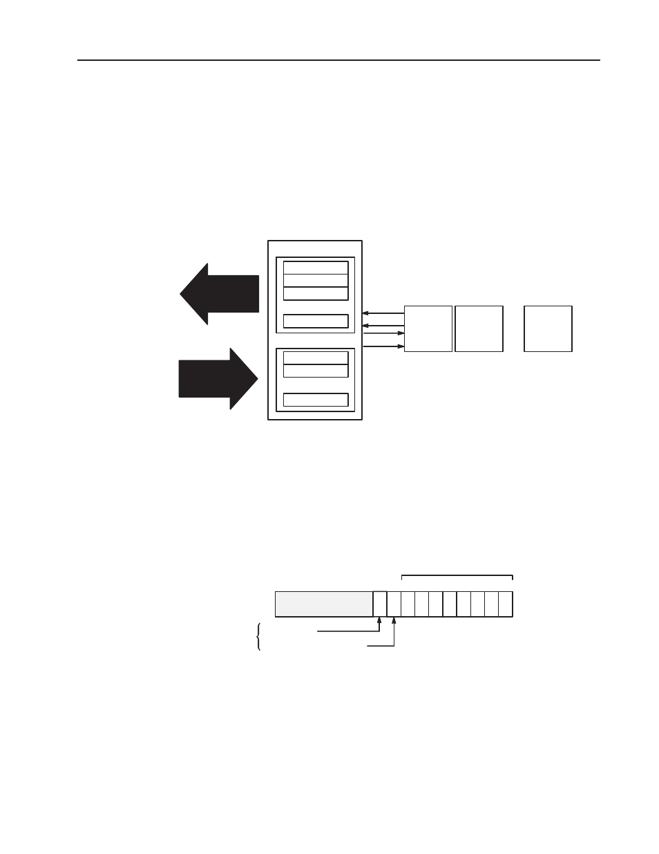
Output data is received by the adapter in the order of the installed
I/O modules. The Output data for Slot 0 is received first, followed
by the Output data for Slot 1, and so on up to slot 7.
The first word of input data sent by the adapter is the Adapter Status
Word. This is followed by the input data from each slot, in the order
of the installed I/O modules. The Input data from Slot 0 is first after
the status word, followed by Input data from Slot 2, and so on up to
slot 7.
Adapter Status
Slot 0 Input Data
Slot 1 Input Data
Slot 7 Input Data
Slot 0 Output Data
Slot 1 Output Data
Slot 7 Output Data
Read Data
Output Data
Network READ
Network WRITE
ControlNet Adapter
Slot 0
I/O Module
Read
Write
Slot 1
I/O Module
Slot 7
I/O Module
...
...
...
...
...
Adapter Input Status Word
The input status word consists of:
•
I/O module fault bits – 1 status bit for each slot
•
node address changed – 1 bit (created by PLC–5 controller)
•
I/O status – 1 bit (created by PLC–5 controller)
15
Bit:
0
1
2
3
4
5
6
7
8
10 through 15
I/O Module Fault Bits
Slot 0
Slot 1
Slot 2
Slot 3
Slot 4
Slot 5
Slot 6
Slot 7
9
I/O State Bit
Not Used
Node Address Changed Bit
Created by PLC-5 controller
The adapter input status word bit descriptions are shown in the
following table.
I/O Structure