Connecting wiring for your pulse counter module – Rockwell Automation 1794-IP4 Series B FLEX I/O PULSE COUNTER User Manual User Manual
Page 25
2–9
How to Install Your Pulse Counter Module
Publication 1794ĆUM016B-EN-P - August 2002
Wiring to the module is made through the terminal base unit on
which the module mounts.
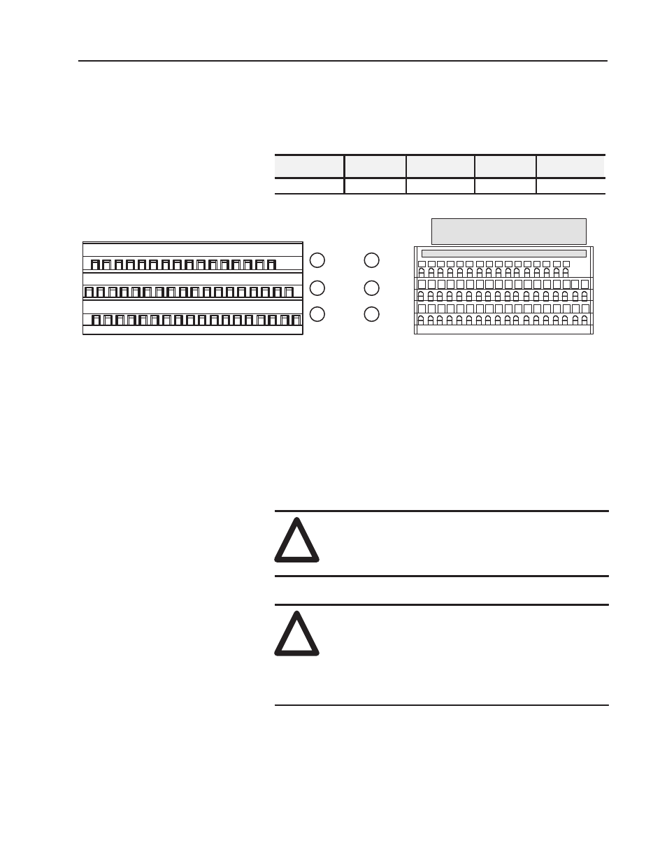
Compatible terminal base units are:
Module
1794ĆTB3
1794ĆTB3S
1794ĆTBN
1794ĆTBNF
1794-IP4
Yes
Yes
Yes
Yes
0
1
2
3 4 5
6 7
8 9 10 11 12 13 14 15
A
B
C
A
B
C
1794ĆTB3
1794ĆTB3S
35 and 51 = common
0 -15
34-51
16-33
34 and 50 = 24V dc
16 17 18 19 20 21 22 23 24 25 26 27 28 29 30 31 32 33
34 35 36 37 38 39 40 41 42 43 44 45 46 47 48 49 50 51
16 and 33 = chassis ground
0
1 2
3 4
5 6
7
8
9 10 11 12 13 14 15
18 19 20 21 22 23
33
24 25 26 27 28 29 30 31 32
17
35 36 37 38
47 48 49 50
34
51
16
Labelplaced at top of wiring area.
39 40 41 42 43 44 45 46
40 thru 45 = chassis ground
35 and 51 = common
34 and 50 = 24V dc
16 and 33 = chassis ground
40 thru 45 = chassis ground
Connecting Wiring using a 1794ĆTB3 and ĆTB3S Terminal Base
Units
1. Connect individual input wiring (N+, N–,) or (D+, D–) to
numbered terminals on the 0–15 row (A) as indicated in the table
below.
!
ATTENTION: Do not connect maximum input
voltage simultaneously to all inputs if the module
ambient temperature is expected to exceed 40
o
C.
!
ATTENTION: If the module ambient temperature is
expected to continuously exceed 40
o
C, you must limit
the input voltage using an external resistor on each
input. A 1K
Ω
resistor effectively limits a 24V sensor
signal to about 15V at the input. Do not limit the input
to less than 6V.
2. Connect the associated input common to the corresponding
terminal on the 16-33 row (B) for each input as indicated in the
table below.
Connecting Wiring for
Your Pulse Counter
Module