Absolute strobe timing – Rockwell Automation 4100 AEC Absolute Encoder Converter Installation User Manual
Page 56
Publication 4100-UM052B-EN-P - October 2001
48 Strobe Position For Applications Not Using the 1394 or Compact
Absolute Strobe Timing
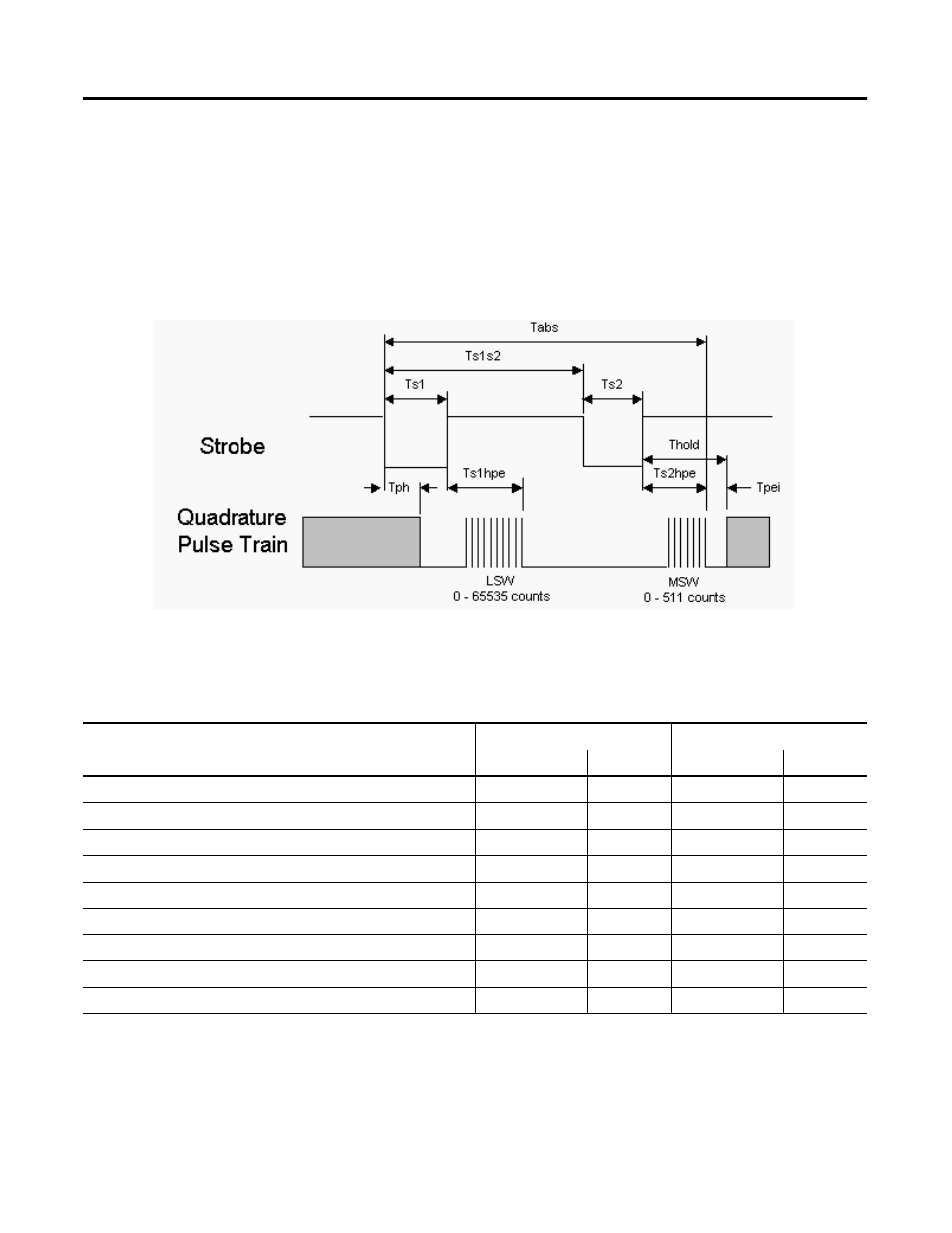
This section defines the timing requirements for the two-strobe pulse
train required for absolute position updates. The AEC must receive
two strobe pulses to initiate and complete an absolute position update
transfer. These are referred to as Ts1 and Ts2 in the data transfer
protocol diagram. The following diagram and table outline the
parametric requirements for an absolute position update cycle.
Figure 18 Absolute Position Transfer Protocol
An absolute position request is an asynchronous event initiated by
the controlling hardware. The first strobe starts the absolute position
update cycle. The first strobe (Ts1) must be active for a minimum of
100ms, but for less than 1000ms to be valid. A strobe is sourcing
Absolute Position Transfer Timing
Parameter
Locked Mode
Free-Running Mode
Min
Max
Min
Max
Tabs (absolute update cycle) = (Ts1s2 + Ts2 + Ts2hpe)
3001ms
Ts1 (Strobe1 active pulse width)
100ms
1000ms
100ms
1000ms
Ts2 (Strobe2 active pulse width)
5ms
1000ms
5ms
1000ms
Ts1s2 (time from Strobe1 inactive to strobe2 active)
Ts1+Ts1hpe+2
2000ms
Ts1+Ts1hpe+2
2000ms
Tph (time from Strobe1 inactive edge to encoder state hold)
30ms
30ms
Ts1hpe (time from Strobe1 inactive to end of encoder stream)
0
25ms
0
25ms
Ts2hpe (time from Strobe2 inactive to end of encoder stream)
0
1ms
0
1ms
Tpei (*time from MSW pulse train end to incremental updating)
0
indefinite
N/A
N/A
Thold
N/A
N/A
500ms
500ms
*Operation mode dependent: Locked or Free-Running