Wiring the aec, Wiring cable flying leads to the plugs – Rockwell Automation 4100 AEC Absolute Encoder Converter Installation User Manual
Page 29
Publication 4100-UM052B-EN-P - October 2001
Installation & Hook-Up 21
Wiring the AEC
There are several connectors on the front of the AEC. All are
duplicated for each axis except the power input connector. Each axis
has two five-pin plugs for connecting the SSI transducer and two
four-pin plugs for connecting a control. In the center is a 2-pin plug
for the power cable. The flying leads wire directly to the screw
terminals on the plugs.
Wiring Cable Flying Leads to the Plugs
To wire the cable leads to the plug:
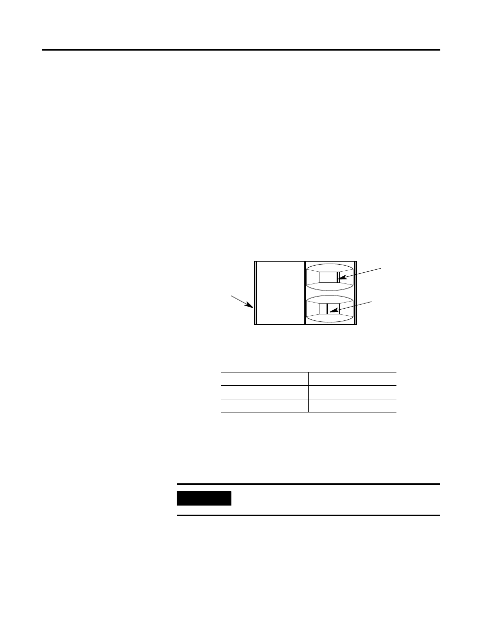
1. Look at the plug to make sure the terminal is open. The
following figure shows both an open and a closed terminal.
Figure 8 Terminal diagram
2.
3. Using a small, flat-head screwdriver, turn the clamping screw
counter-clockwise several times.
4. Using a proper stripping tool, strip the wire insulation back on
the cable lead.
5. Trim the cable lead so that 0.275 inches of metal wire is
exposed.
6. Insert the cable lead in the appropriate terminal. Refer to the
proper figures for their locations.
Terminal Steps
If the terminals are:
Do this:
Not open
Go to step 3
Open
Go to step 4
IMPORTANT
All terminals accommodate a maximum of 14 gauge
wire.
Terminal open
Terminal closed
Clamping screws